
System and process for manufacturing application specific printable circuits (ASPC'S) and other custom electronic devices

Inactive Publication Date: 2006-08-24
CABOT CORP
View PDF99 Cites 25 Cited by
  • Summary
  • Abstract
  • Description
  • Claims
  • Application Information

AI Technical Summary

Benefits of technology

[0009] It is therefore a general object of the invention to provide a non-contact direct printing system that will obviate or minimize problems of the type previously described.
[0010] It is a specific object of the present invention to provide a system and process for printing interconnections between pre-printed, low cost transistors and / or logic cells that have been printed and / or mounted on a low cost substrate with pads of sufficient size to allow printing of the interconnects between these devices.
[0011] It is a specific object of the present invention to provide a system and process for printing interconnections between pre-printed, low cost transistors and / or logic cells that have been printed and / or mounted on a low cost substrate with pads of sufficient size to allow printing of the interconnects between these devices such that mass production of circuit functions with more complex semiconductor pre-printed media. It is still a further object of the present invention to provide a system and process for printing interconnections between the more complex semiconductor pre-printed media that can then be customized at a user's convenience by a direct printing process that is done regionally based on a specific circuit design.

Problems solved by technology

The problem for many of these applications, however, is that the active devices needed to make them functional (transistors, display components, electronic memory, logic circuits, RFID and radio circuits, and others) often require high precision patterning techniques, clean room environments and other special processes that make them cost prohibitive for regional manufacturing using conventional printing equipment.
Often larger functional logic blocks (like a processor or memory circuit) were included and these devices were then called “standard cells.” But, there was no practical way to combine the ASIC's and standard cells with printable electronic inks.
But to date, the printing of semiconductors and displays has required far more complex processes for either organic or inorganic semiconductor materials to be deposited and turned into a functional transistor or other logic devices.
Making custom printed circuits on low cost substrates with these processes would therefore require the customer to have either a very complex and sophisticated process equipment with many layers patterned, or originate a custom design for each new device.
Furthermore, current circuit manufacturing techniques do not allow for quick and cost-effective customization of conventional or new circuit boards.
Therefore, it is very difficult and expensive to modify circuit boards that already have circuitry on them to customize or modify for a new function or use.

Method used


Image

  • System and process for manufacturing application specific printable circuits (ASPC'S) and other custom electronic devices
  • System and process for manufacturing application specific printable circuits (ASPC'S) and other custom electronic devices
  • System and process for manufacturing application specific printable circuits (ASPC'S) and other custom electronic devices

Examples


Embodiment Construction

[0112] The various features of the preferred embodiment(s) will now be described with reference to the drawing figures, in which like parts are identified with the same reference characters. The following description of the presently contemplated best mode of practicing the invention is not to be taken in a limiting sense, but is provided merely for the purpose of describing the general principles of the invention. This application is also related to co-pending U.S. Non-provisional Patent Application Ser. No. , filed on Jan. 13, 2006, entitled “A System and Process for Manufacturing Custom Electronics by Combining Traditional Electronics with Printable Electronics,” by Chuck Edwards.

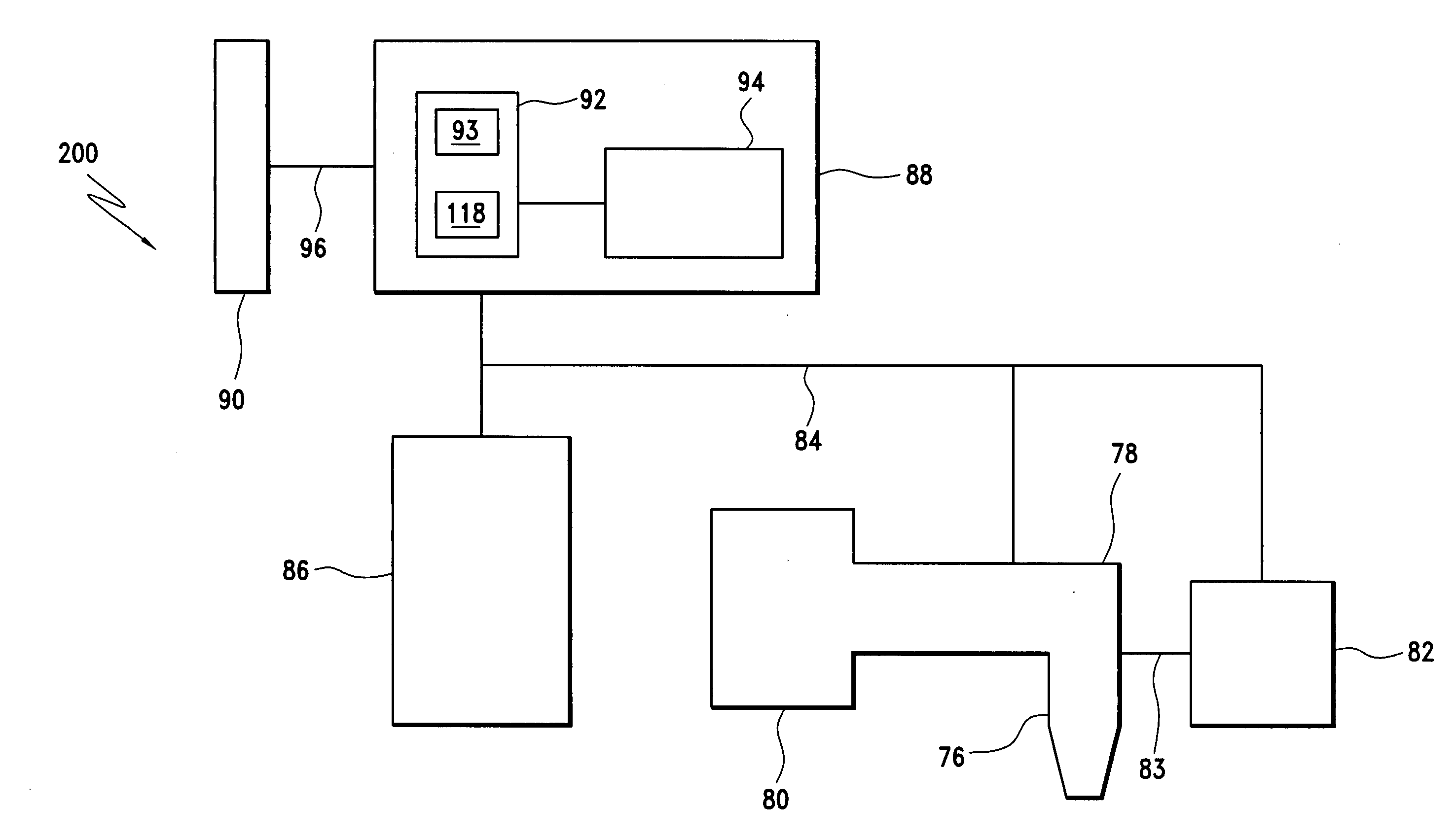
[0113]FIG. 1 illustrates a block diagram of a direct printing system 200 that can be used to manufacture application specific printable circuits (ASPC's) according to an embodiment of the present invention. Many different types of direct printing processes can be used to manufacture ASPC's or custom cir...


PUM


Abstract

A system and process for manufacturing custom printed circuit boards on pre-provided substrates, wherein the substrate can be pre-provided with electronic devices. The electronic devices can be pre-provided on the substrate by direct printing, or in a more conventional manner, such as by standard integrated circuit technologies, in many different packing technologies. The user designs the custom printed circuit board using a design tool to perform one or more specific electronic functions, based on the pre-provided electronic devices, and / or custom designed and direct printed electronic devices. The electronic devices includes transistors, resistors, capacitors, among other types of devices. Examples of the electronic functions that can realized using the system and process described herein include, but are not limited to, include an RFID device, and a PROM.

Description

CROSS REFERENCE TO RELATED APPLICATIONS [0001] This application claims priority to U.S. Provisional Patent Application Ser. Nos. 60 / 695,411 filed Jul. 1, 2005 and 60 / 643,577, 60 / 643,629, and 60 / 643,378, all filed on Jan. 14, 2005, the entireties of which are incorporated herein by reference.BACKGROUND OF THE INVENTION [0002] 1. Field of the Invention [0003] The invention relates to direct printing. More particularly, the invention relates to a system and process for non-contact direct printing using conductive particles in an ink solution for dispersion on substrates that contain other electronic circuits to create one or more new electronic functions. [0004] 2. Background Art [0005] Printable electronic inks, and other new “paper-like” display technologies such as E Ink, have developed as an advanced process of producing electronics and displays on paper-like materials and films. These low cost electronics promise to dramatically reduce costs and increase the number and variety of ...

Claims


Application Information

Patent Timeline
IPC IPC(8): G06F17/50
CPCH01L21/485H01L2224/95101H01L23/5382H01L2924/09701H01L2924/12044H01L2924/3011H05K1/0286H05K1/16H05K3/0005H05K3/125H05K3/32H05K3/4664H05K2201/10166H05K2201/10212H05K2203/013H05K2203/1469H01L24/95H01L21/6715H01L2924/15787H01L2924/12041H01L2924/14H01L2924/00
Inventor EDWARDS, CHUCK
Owner CABOT CORP
Learn More