
Regulating charge pump

a charge pump and charge tube technology, applied in charge amplifiers, amplifiers with semiconductor devices/discharge tubes, galvano-magnetic amplifiers, etc., can solve the problems of poor voltage regulation and said run out of headroom, and achieve the effect of substantially reducing the headroom required by the regulating amplifier and reducing the battery cost in electronic systems

Inactive Publication Date: 2006-08-17
ZYWYN CORP
View PDF7 Cites 98 Cited by
  • Summary
  • Abstract
  • Description
  • Claims
  • Application Information

AI Technical Summary

Benefits of technology

The present invention is a new way to regulate the output of a charge pump by using both charge pumps and regulators in a feedback configuration. This allows for precise regulation regardless of the characteristics of the charge pump, load current, temperature, or signal frequency. It also reduces the need for high-voltage batteries, reducing battery cost in electronic systems. The use of low-voltage batteries with fewer cells provides precision control for circuits that require higher voltages. The invention also reduces the headroom required by the regulating amplifier by a factor 1/N, where N is the voltage multiplication of the charge pump. The typical charge pumps used in the invention are 1.5×, 2×, 3×, etc.

Problems solved by technology

The technical problem addressed in this patent is the need for electronic circuitry that can operate from a single battery with efficient circuitry to minimize load currents, provide good voltage regulation, and utilize the battery until the maximum energy has been extracted. The text also discusses the use of charge pumps and the limitations of poor voltage regulation due to loading current sensitivity. The text concludes with the introduction of the Low Drop Out (LDO) regulator, which is a voltage or current regulator that can operate over a wide supply voltage range, including very low supply voltages.

Method used


Image

  • Regulating charge pump
  • Regulating charge pump
  • Regulating charge pump

Examples


Embodiment Construction

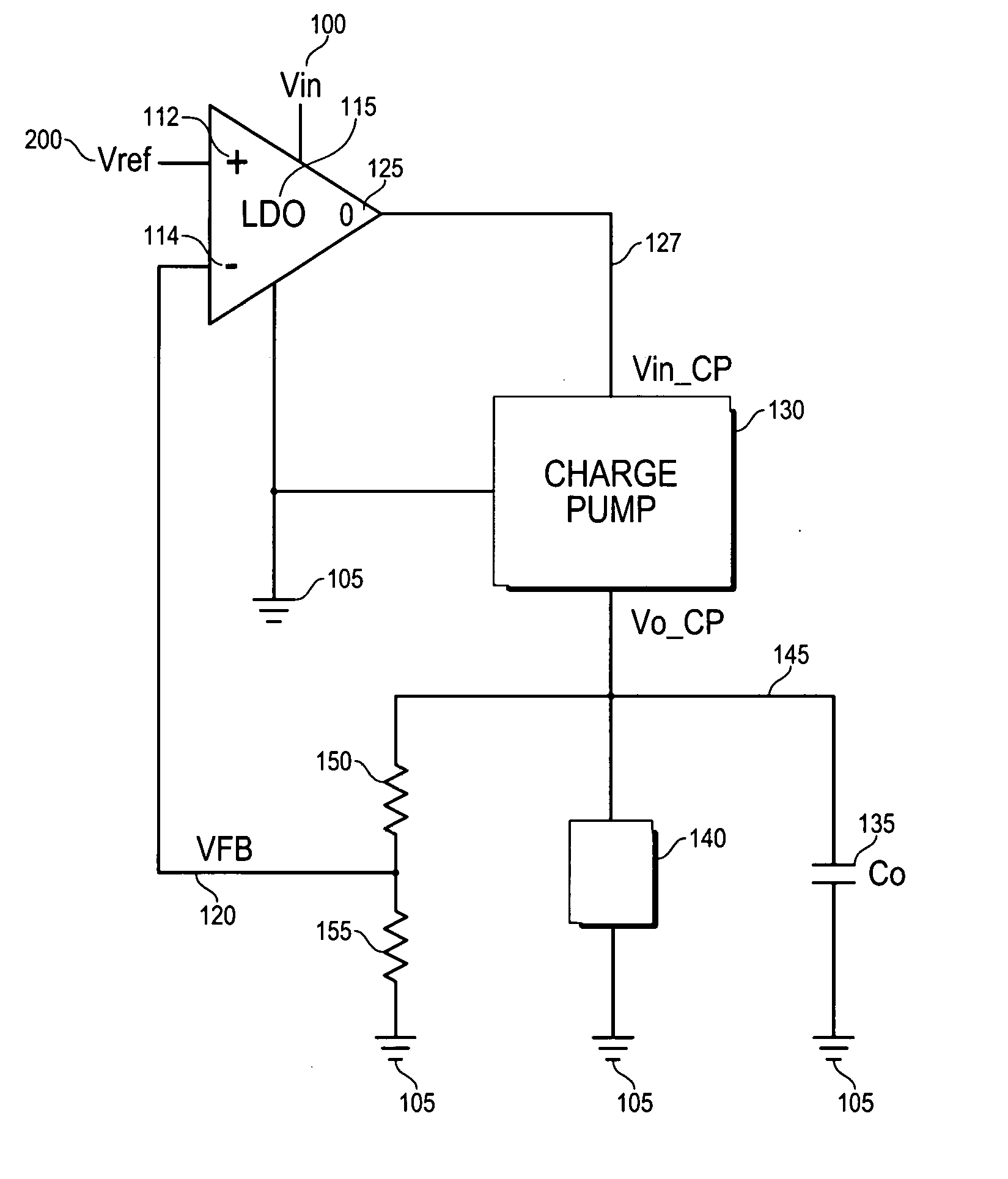
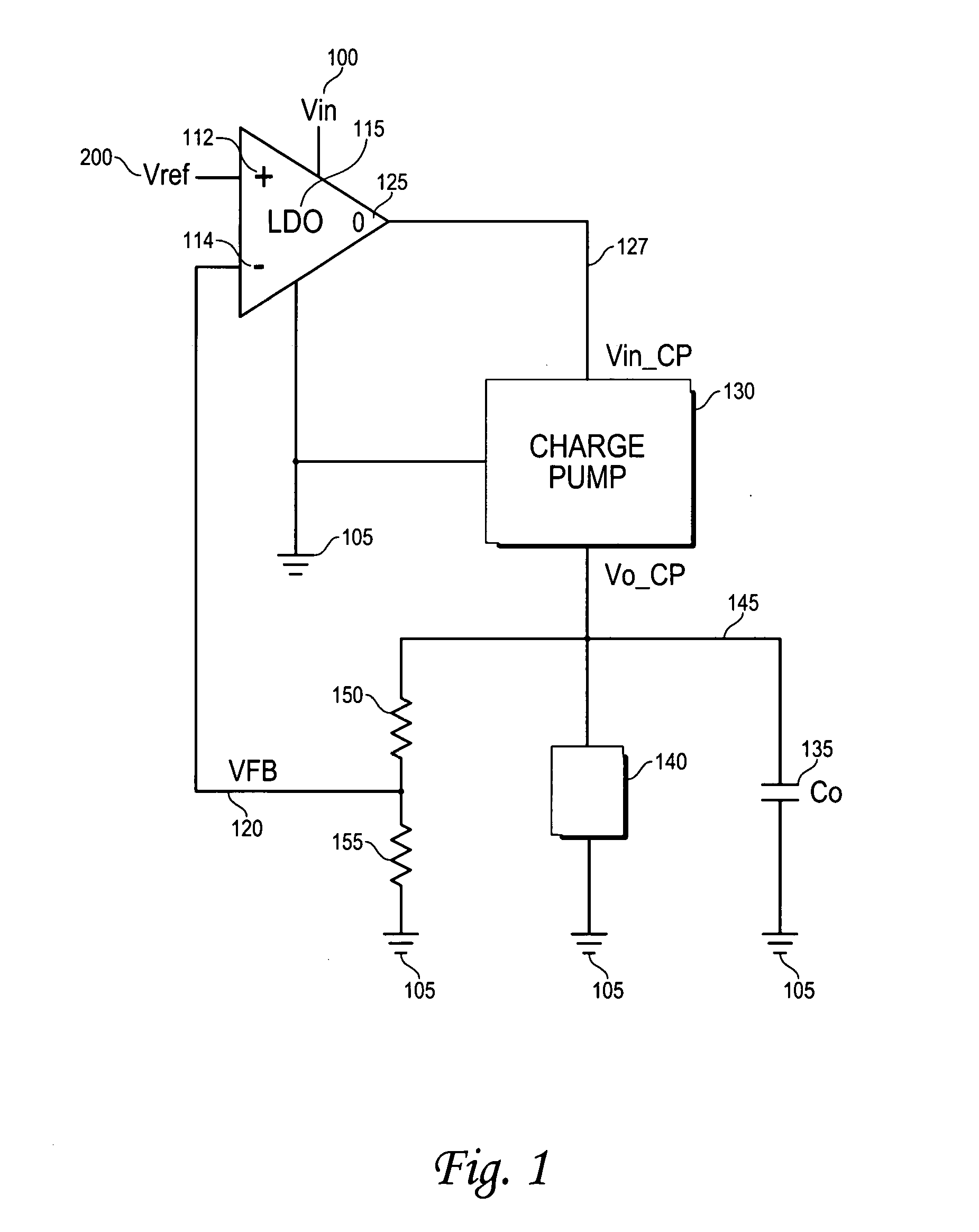
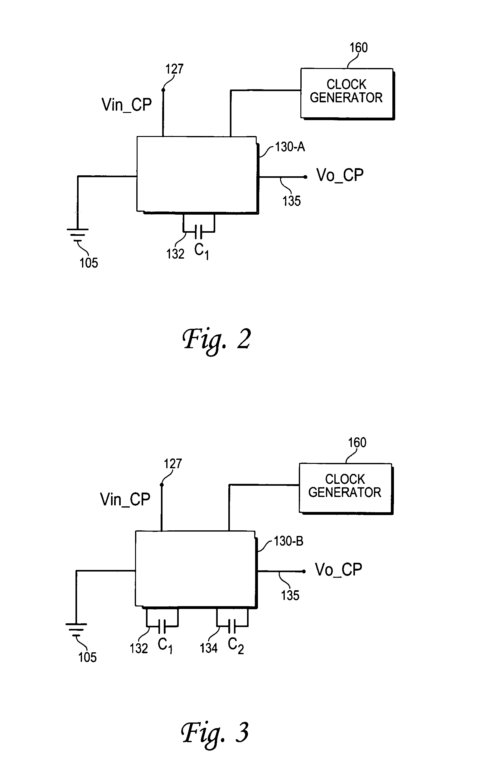
[0013] Referring to FIG. 1, a regulated output voltage source useable in a variety of circuits is generated at output Vo-cp 145. Voltage energy source Vin 100 and ground 105 from power supply or battery, not shown, supply LDO 115 with power. Vref 110 is the input voltage reference for the circuit and is connected to LDO non-inverting input 112, and represents the desired voltage to which the Regulating Charge Pump (RCP) of the invention is to regulate its output, Vo-cp 145. LDO regulators are common in the field of electronics and may be manufactured using common silicon fabrication techniques and employing bipolar and / or Metal Oxide Semiconductor (MOS) and / or Complimentary Metal Oxide Semiconductor (CMOS) or other common integrated circuit technologies and are well known in the art. The output of LDO 115 at connection 125 is coupled to the input terminal Vin-cp 127 of charge pump 130, which also has a connection to ground 105 and utilizes clock circuitry not shown. Clock circuits a...


PUM


Abstract

A regulating charge pump includes a variable-configuration charge pump in combination with a linear regulator, the charge pump arranged within the linear regulator feedback loop to accurately control the charge pump output current or voltage. A charge pump of voltage gain N is utilized to advantageously reduce headroom required in a regulator circuit by substantially 1/N.

Description


Claims


Application Information

Patent Timeline
Owner ZYWYN CORP
Learn More