
Optimized power supply system for an electronic circuit

a technology of power supply system and electronic circuit, which is applied in the direction of ignition automatic control, high-level techniques, instruments, etc., can solve the problems of insufficient power supply voltage setting, inability to receive a message correctly, and insufficient power supply voltage. , to achieve the effect of reducing battery costs, saving energy, and increasing the operating time of the apparatus

Inactive Publication Date: 2002-04-02
WSOU INVESTMENTS LLC
View PDF25 Cites 6 Cited by
  • Summary
  • Abstract
  • Description
  • Claims
  • Application Information

AI Technical Summary

Benefits of technology

An object of the present invention is thus to provide a better solution, tending better than the prior art solution towards optimum adjustment of the power supply voltage, so as to save energy, in order to increase the operating time of the apparatus between battery recharging or battery replacement, or in order to reduce battery costs.

Problems solved by technology

Unfortunately, the conditions surrounding the apparatus can change considerably from the time at which it is switched on to the time at which it is actually used.
Thus, under such conditions, if the power supply voltage of the pager really were at its minimum value, such a drop in the temperature of the apparatus could make it incapable of receiving a message correctly.
Consequently, the power supply voltage setting is not genuinely optimum.
In which case, the power supply voltage is not set optimally either.

Method used


Image

  • Optimized power supply system for an electronic circuit
  • Optimized power supply system for an electronic circuit
  • Optimized power supply system for an electronic circuit

Examples


Embodiment Construction

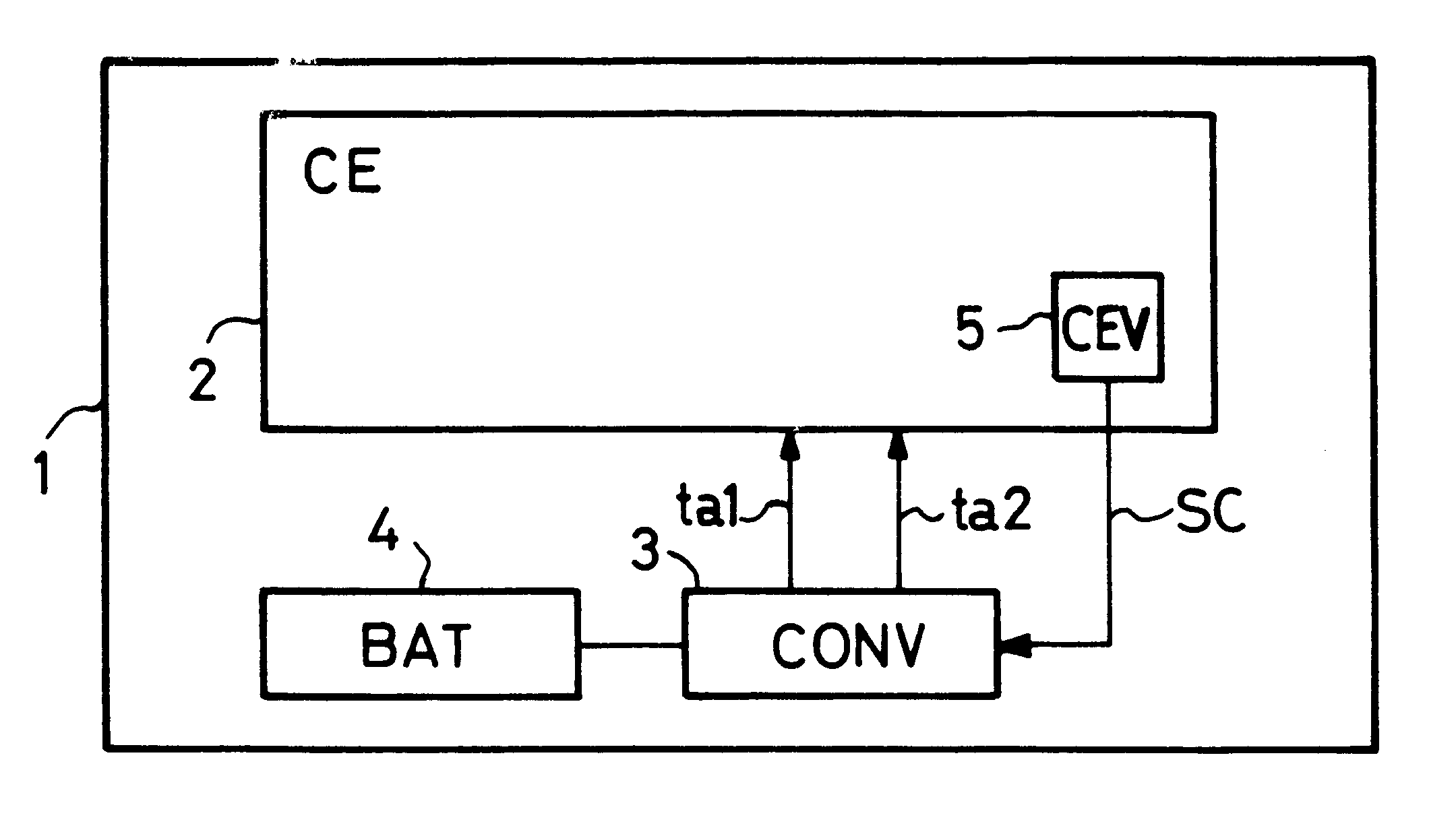
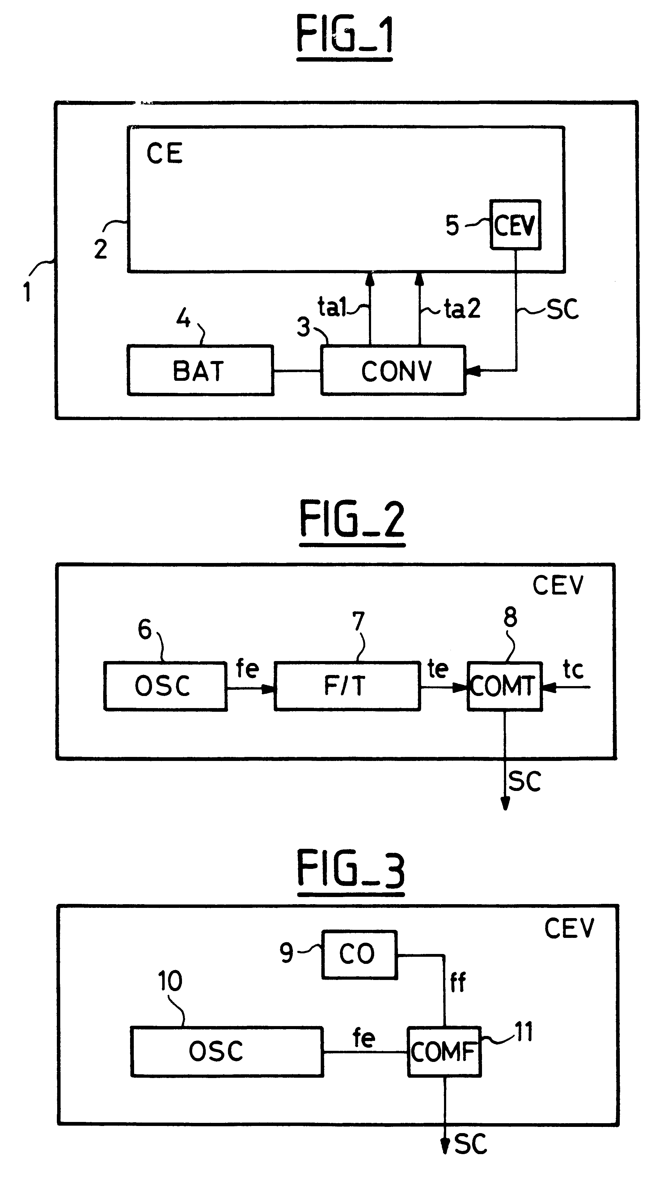
The general diagram in FIG. 1 shows portable apparatus 1 which may, for example, be a radiotelephone essentially comprising an electronic circuit 2, referred to as "CE", which is powered via a DC-to-DC power supply voltage converter 3, referred to as "CONV", from an energy source 4 which is conventionally a rechargeable battery "BAT". The converter CONV delivers at least one DC power supply voltage ta1, and it can deliver at least one second power supply voltage ta2.

The man-machine interface elements, such as the screen, the keypad, etc, that are nearly always to be found on such portable electronic apparatus, together with the electronic circuit CE, and that can be powered without any specific problems being encountered, are not described herein, nor are they shown in the figures.

With commonly-used technology, the electronic circuit CE may be implemented in the form of an integrated circuit comprising one or more chips made of semiconductor material. The invention is applicable reg...


PUM


Abstract

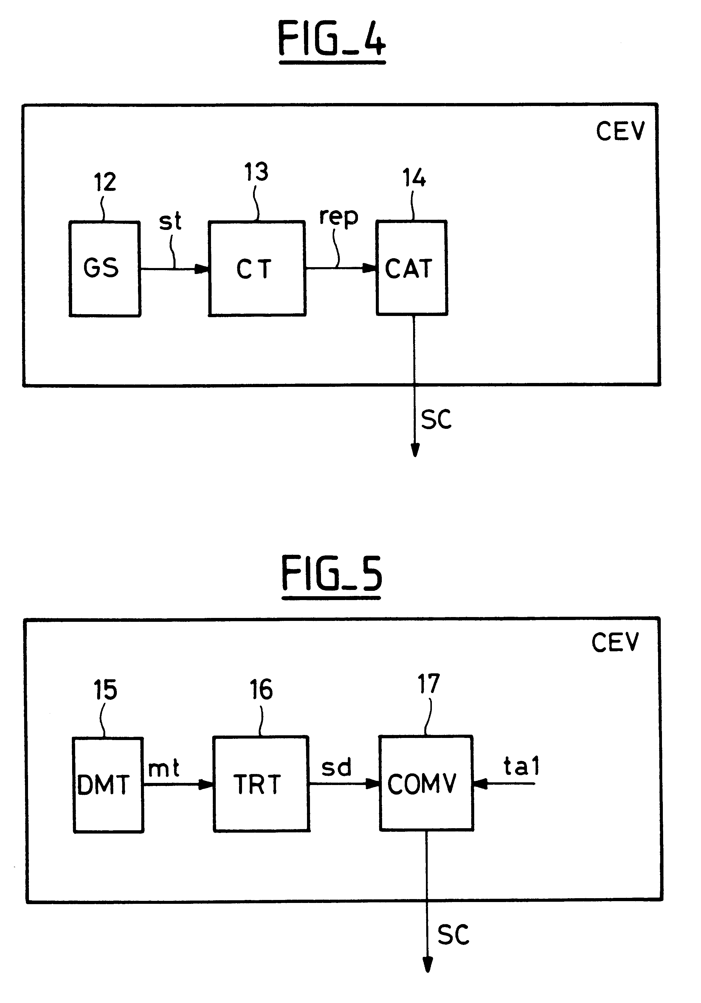
Electronic evaluation device provided within an electronic circuit so as to deliver an indication of the operating conditions of the electronic circuit, which indication is used to adjust the power supply voltage to a minimum value at which the electronic circuit can still operate correctly.

Description

The present invention relates to an optimized power supply system for an electronic circuit.A system of this type is already known, e.g. from Patent Document U.S. Pat. No. 5,218,705. The electronic circuit in question is contained in receiver apparatus for receiving personal messages and commonly referred to as a "pager". The power supply voltage for the electronic circuits of the pager is delivered via a variable-voltage DC-to-DC voltage converter from a rechargeable battery or from a non-rechargeable battery. To save energy, and therefore to increase the operating time of the pager between battery recharging or battery replacement, or to reduce battery costs, the power supply voltage is adjusted to an operating value. The operating value is determined on initializing operation of the pager, by taking into account the data rate at which the pager is to receive data, and it cannot be less than a minimum operating voltage. The minimum operating voltage is also determined on initializ...

Claims


Application Information

Patent Timeline
Patent Type & Authority Patents(United States)
IPC IPC(8): H04Q7/18H02J1/00H04W52/02G06F1/32H04W88/02
CPCH04W52/0258H04W88/022Y02B60/50Y02D30/70
Inventor ATTIMONT, LUCADDRA, MODESTE
Owner WSOU INVESTMENTS LLC
Learn More