Vapor collection method and apparatus
- Summary
- Abstract
- Description
- Claims
- Application Information
AI Technical Summary
Benefits of technology
Problems solved by technology
Method used
Image
Examples
example 1
[0089] With reference to FIG. 7, an oven 100 with a direct fired heater box 102 was utilized in the present Example. The oven 100 had a supply air plenum 104 with multiple high velocity nozzles 106. These high velocity convection nozzles 106 were placed within 2.5 cm from the substrate material 108. The material 108 was a web of plastic film having a semi-rigid vinyl dispersion coated on the surface. The high velocity nozzles 106, provided high heat transfer to the material 108. The discharge air velocity at the nozzle exit was 20-30 meters per second at the oven temperature. The heater box had a recirculation fan 110 and a modulating direct fired burner 112. The heater box mixed the recirculation air 114 with fresh make up air 116 and passed this through the heater box 102. The direct fired burner 112 was modulated to control discharge air temperature at 150° to 200° C. The desired operating pressure of the oven is maintained by controlling oven exhaust 118 and the make up air 116....
examples 2-5
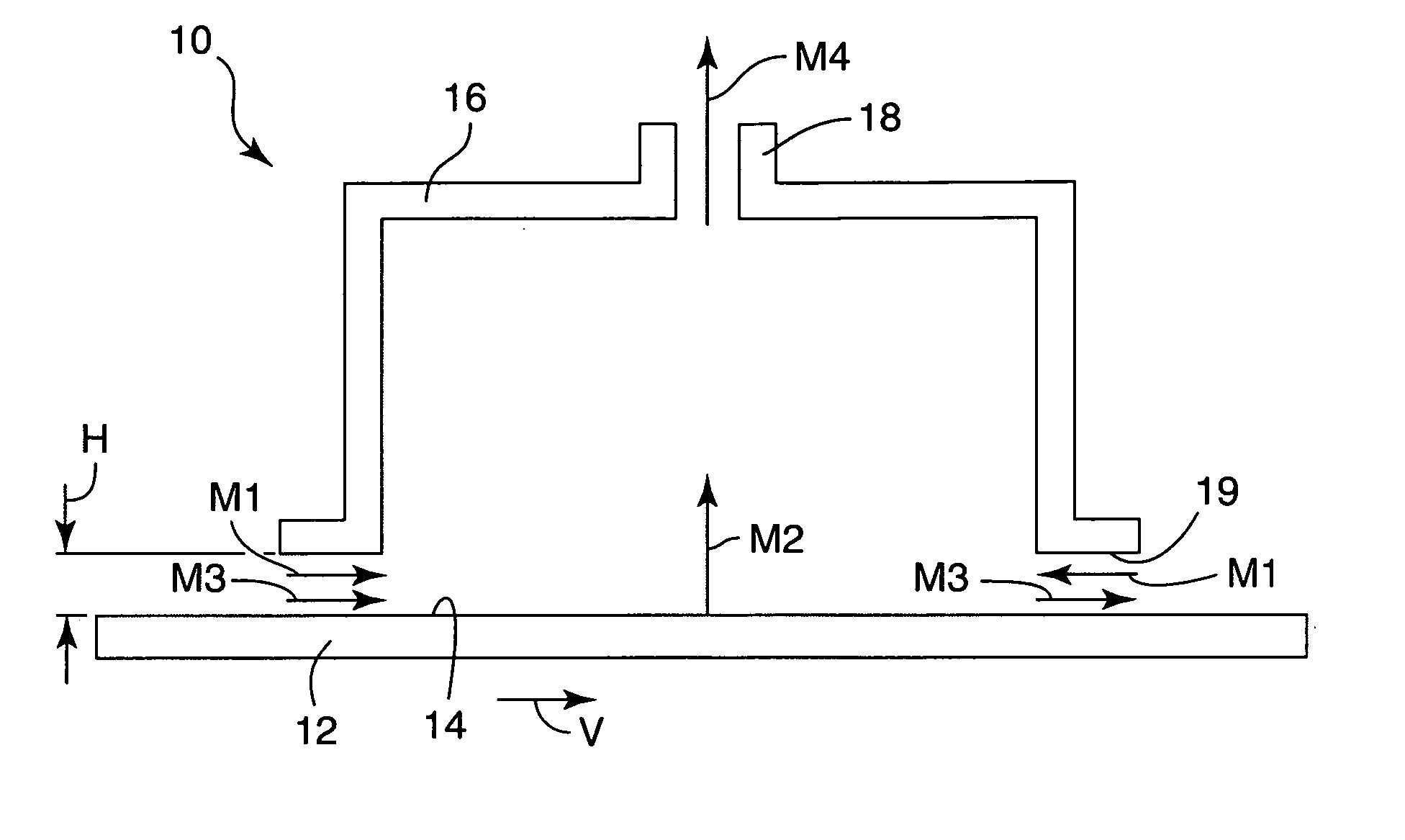
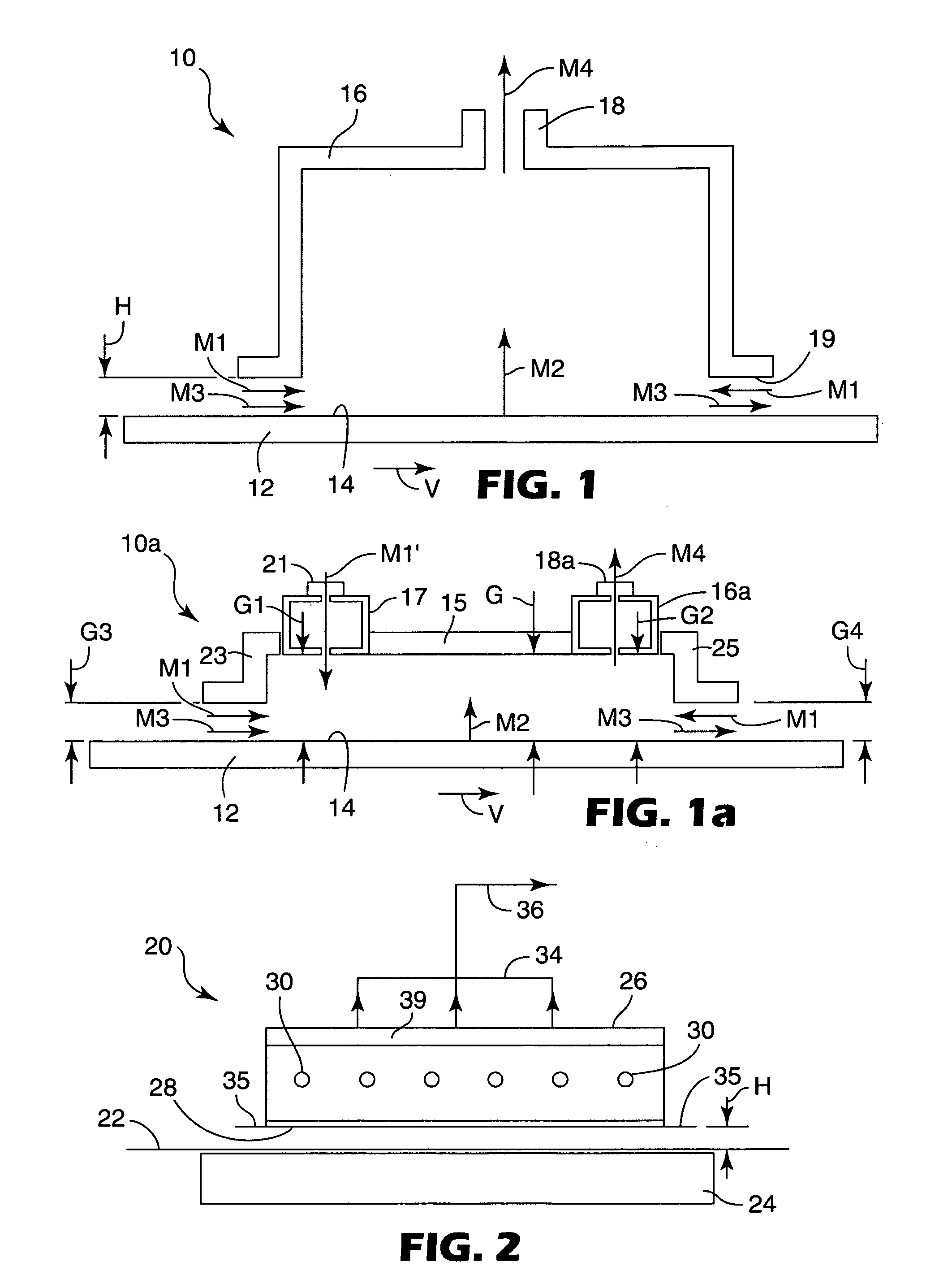
[0090] The comparison table below, Table 1, provides example calculations for different systems at typical equipment configurations and operating conditions. The definitions for M1, M2, M3, and M4 are the same as described above. M5 represents the time-average mass flow per unit width of any additional dilution stream provided to the chamber (for example the makeup air stream in convection ovens) in kg / second / meter. The width (“w”) of the material, in centimeters, is the measurement (of the gap) in the direction perpendicular to the motion of the material. The time-average gas phase velocity (“”) was defined above and has units of meters per second. The pressure difference (“ΔP”) is the pressure gradient between the lower periphery of the chamber and outside the chamber in Pascals. The material velocity (“V”) is measured in meters per second.
[0091] The average velocity of gas phase components through the gap, , can be measured using a velocity meter such as a hot wire anemometer, c...
example 4
[0094] In this example the vapor collection apparatus was integrated with a conventional gap drying system to capture and collect the gas phase components exiting the gap dryer. The web was conveyed by a conveying system through the apparatus of the present invention. The web was comprised of polyester film coated with inorganic material dispersed in ethanol and water. The web entered through an entrance gap having a width, w, of 30.5 cm and a height, H, of 0.32 cm.
[0095] The material exited through an exit gap having the same dimensions as the entrance gap. The web was transported through the gap and underneath the chamber at a velocity of 0.015 meter / second. The exhaust flow M4 was measured to be 0.0066 kg / second / meter. The flow through the entrance and exit gaps out of the chamber, M1, resulting from the induced pressure gradient was approximately the same, 0.0066 kg / second / meter. M1 was calculated using Equation 1. The web and coating were for all practical purposes dry upon ex...
PUM
 Abstract
Description
Claims
Application Information
 - R&D
- Intellectual Property
- Life Sciences
- Materials
- Tech Scout
- Unparalleled Data Quality
- Higher Quality Content
- 60% Fewer Hallucinations
Browse by: Latest US Patents, China's latest patents, Technical Efficacy Thesaurus, Application Domain, Technology Topic, Popular Technical Reports.
© 2025 PatSnap. All rights reserved.Legal|Privacy policy|Modern Slavery Act Transparency Statement|Sitemap|About US| Contact US: help@patsnap.com


