Lighting control unit for vehicle lighting fixture

a technology for vehicle lighting and control units, which is applied in process and machine control, electric devices, instruments, etc., can solve the problems of increased costs, led failure to illuminate, and lowered system safety, so as to prevent damage to circuit elements, and reduce the risk of system failur

Inactive Publication Date: 2006-08-10
KOITO MFG CO LTD
View PDF4 Cites 12 Cited by
  • Summary
  • Abstract
  • Description
  • Claims
  • Application Information

AI Technical Summary

Benefits of technology

[0023] (Operation) By forcibly stopping the ON operation of the switching element when the voltage applied to a semiconductor light source has exceeded the second set voltage that is higher than the first set voltage, it is possible to reliably prevent damage to the circuit element.
[0024] As understood from the foregoing description, according to the lighting control unit for a vehicle lighting fixture of claim 1, it is possible to suppress a sudden rise in the output voltage of the switching regulator with a fault in a semiconductor light source, thus prevent damage to the circuit element.
[0025] According to the lighting control unit for a vehicle lighting fixture of claim 2, it is possible to suppress a sudden rise in the output voltage of the switching regulator with a fault in a semiconductor light source, thus prevent damage to the circuit element even in case a plurality of semiconductor light sources are provided.
[0026] According to the third aspect of the invention, it is possible to reliably prevent damage to the circuit element.

Problems solved by technology

This makes it necessary to use an LED with a pressure resistance that will not go faulty when the output voltage of the switching regulator exceeds 120V, which increases costs.
When too low a set voltage is specified in the configuration where the switching element is turned off when the output voltage of the switching regulator has exceeded the set voltage, variations in Vf (forward voltage) of an LED may result or the LED may fail to illuminate depending on the corresponding temperature characteristic.
In particular, when an LED with a high Vf is used at low temperatures, it may cause the LED to illuminate despite a wire break, which will lower the system safety.
When the secondary side of the transformer is open with the wire break in the LED, the transformer has no energy delivery port on the secondary side thus resulting in magnetic saturation at a lower current value caused by the absence of the gap unless the primary side and the secondary side are coupled again.
This could damage the switching element without proper action being taken.
However, it is difficult to match the degree of lowering the duty ratio of the switching signal with the degree of magnetic saturation of the transformer.
Too high a degree of lowering the duty ratio of the switching signal could result in variations in the Vf of the LED or the LED could fail to illuminate depending on the temperature characteristic.
This could impair the safety of the system.
The energy could damage the switching element when the switching element consumes the suddenly elevated current at the time of wire break, leading to power loss.

Method used


Image

  • Lighting control unit for vehicle lighting fixture
  • Lighting control unit for vehicle lighting fixture
  • Lighting control unit for vehicle lighting fixture

Examples


Embodiment Construction

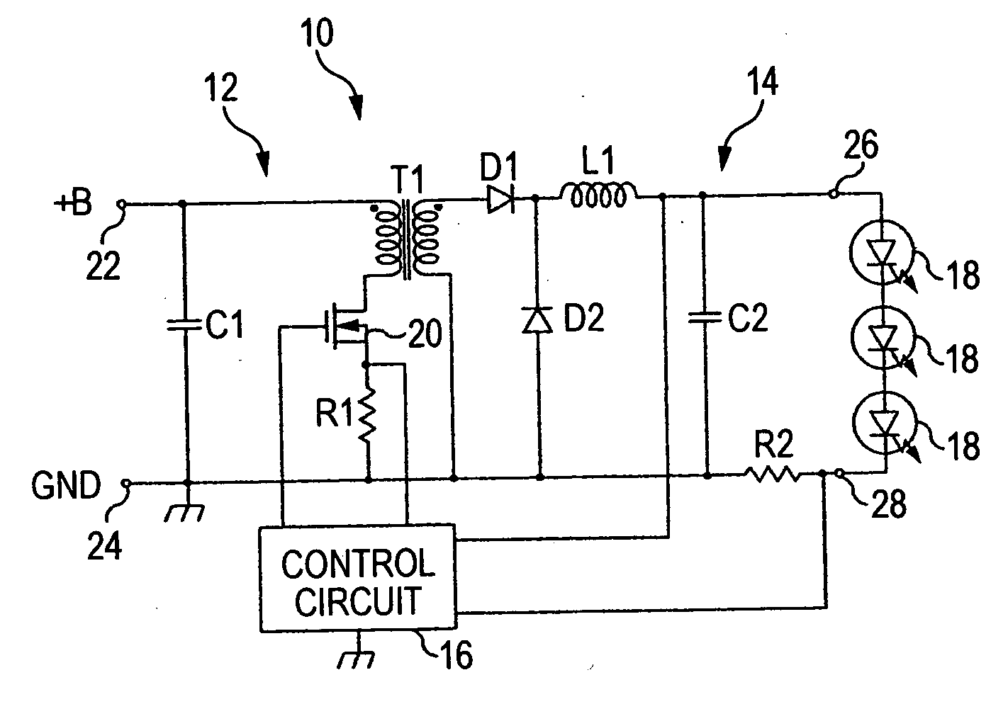
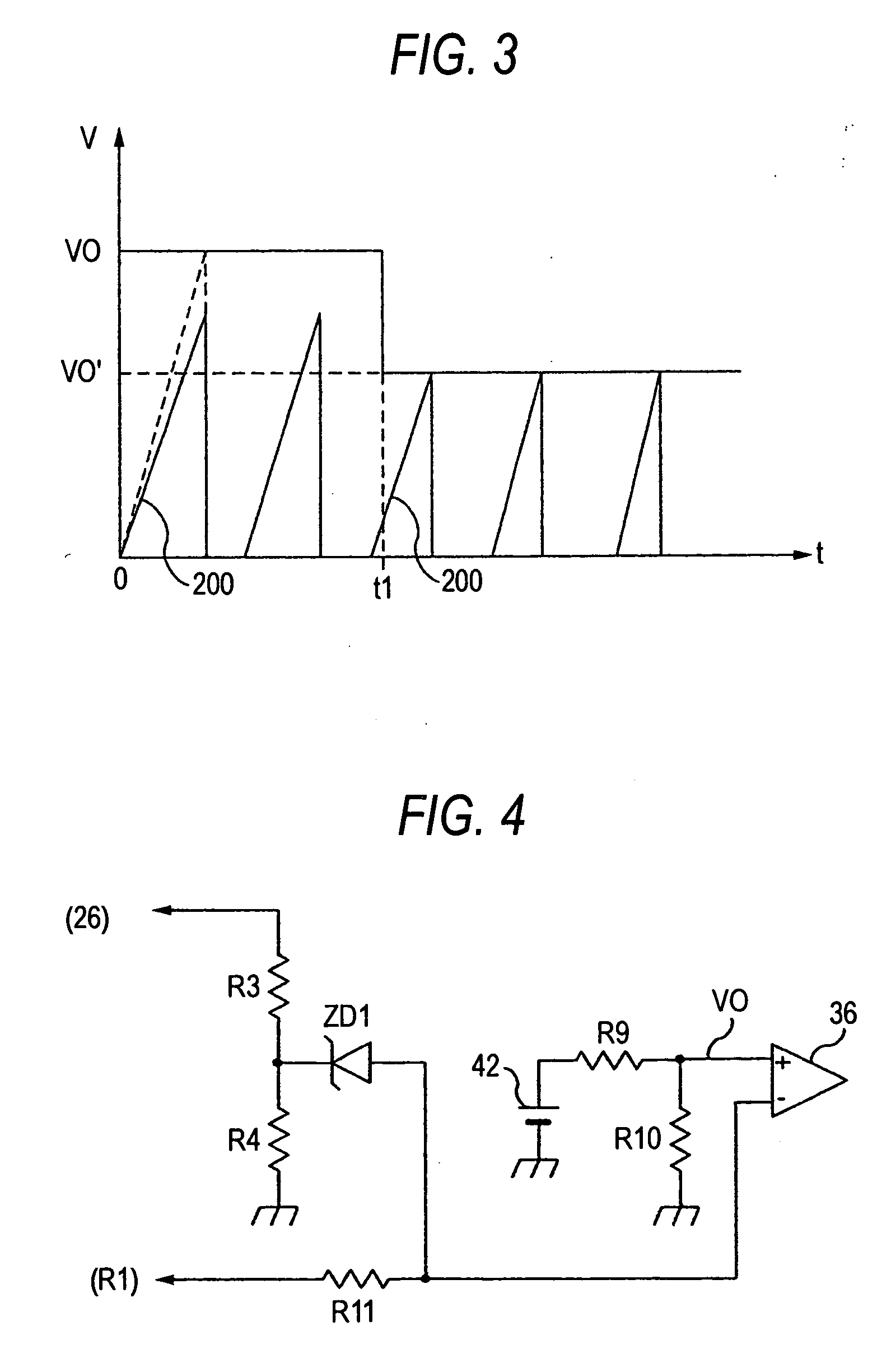
[0034] Next, embodiments of the invention will be described by way of examples with reference to the figures. FIG. 1 is a block diagram of a lighting control unit for a vehicle lighting fixture showing a first embodiment of the invention. FIG. 2 is a circuit block diagram showing a first embodiment of a control circuit. FIG. 3 is a waveform diagram illustrating the operation of the control circuit of the first embodiment. FIG. 4 is a circuit block diagram showing a second embodiment of the control circuit. FIG. 5 is a waveform diagram illustrating the operation of the control circuit of the second embodiment. FIG. 6 is a block diagram of the lighting control unit for a vehicle lighting fixture showing a second embodiment of the invention. FIG. 7 is a circuit block diagram showing a third embodiment of the control circuit.

[0035] As shown in FIG. 1, a lighting control unit for a vehicle lighting fixture 10 has, as one component of a vehicle lighting fixture, a forward type switching ...


PUM


Abstract

In a process where the energy accumulated in the transformer while a transistor is turned ON is emitted to an output circuit and an LED is illuminated with the emitted energy, a voltage generated across a resistor is monitored by a control circuit. When the current flowing through the transistor has reached a limit current value, the ON operation of the transistor is limited. When the output voltage of the output circuit has exceeded a first set voltage, the limit current value is lowered and the ON operation of the transistor is further limited. When the output voltage of the output circuit has exceeded a second set voltage, the ON operation of the transistor is forcibly stopped.

Description

CROSS-REFERENCE TO RELATED APPLICATIONS [0001] This application is based upon and claims the benefit of priority from the prior Japanese Patent Applications No. 2005-032436, filed on Feb. 9, 2005, the entire contents of which are incorporated herein by reference. BACKGROUND OF THE INVENTION [0002] 1. Field of the Invention [0003] The present invention relates to a lighting control unit for a vehicle lighting fixture and in particular to a lighting control unit designed to control lighting of a semiconductor light source including a semiconductor light-emitting device. [0004] 2. Description of the Related Art [0005] In the related art, a vehicle lighting fixture is known that uses a semiconductor light-emitting device such as an LED (Light Emitting Diode). This type of vehicle lighting fixture mounts a lighting control circuit for controlling lighting of an LED. [0006] A lighting control circuit has been proposed in which for example a forward type switching regulator is used as a sw...

Claims


Application Information

Patent Timeline
Patent Type & Authority Applications(United States)
IPC IPC(8): B60L1/00B60Q1/00B60Q11/00H01L33/00H05B37/02
CPCH05B33/0815H05B45/345H05B45/382
Inventor MURAKAMI, KENTAROUITO, MASAYASU
Owner KOITO MFG CO LTD
Why Eureka
Try Eureka