
Tool geometries for friction stir spot welding of high melting temperature alloys

a high melting temperature alloy and tool geometrie technology, applied in the direction of manufacturing tools, soldering devices, auxillary welding devices, etc., can solve the problems of high energy cost, hazardous fumes, rsw technology, etc., and achieve the effect of enabling fssw of high melting temperature materials and enhancing mixing of high temperature materials

Inactive Publication Date: 2006-08-10
MAZAK CORP +2
View PDF17 Cites 48 Cited by
  • Summary
  • Abstract
  • Description
  • Claims
  • Application Information

AI Technical Summary

Benefits of technology

[0030] It is an aspect of the present invention to provide a tool geometry that enables FSSW of high melting temperature materials.
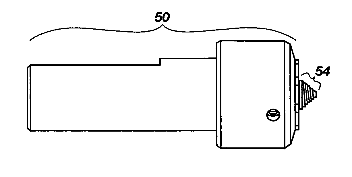
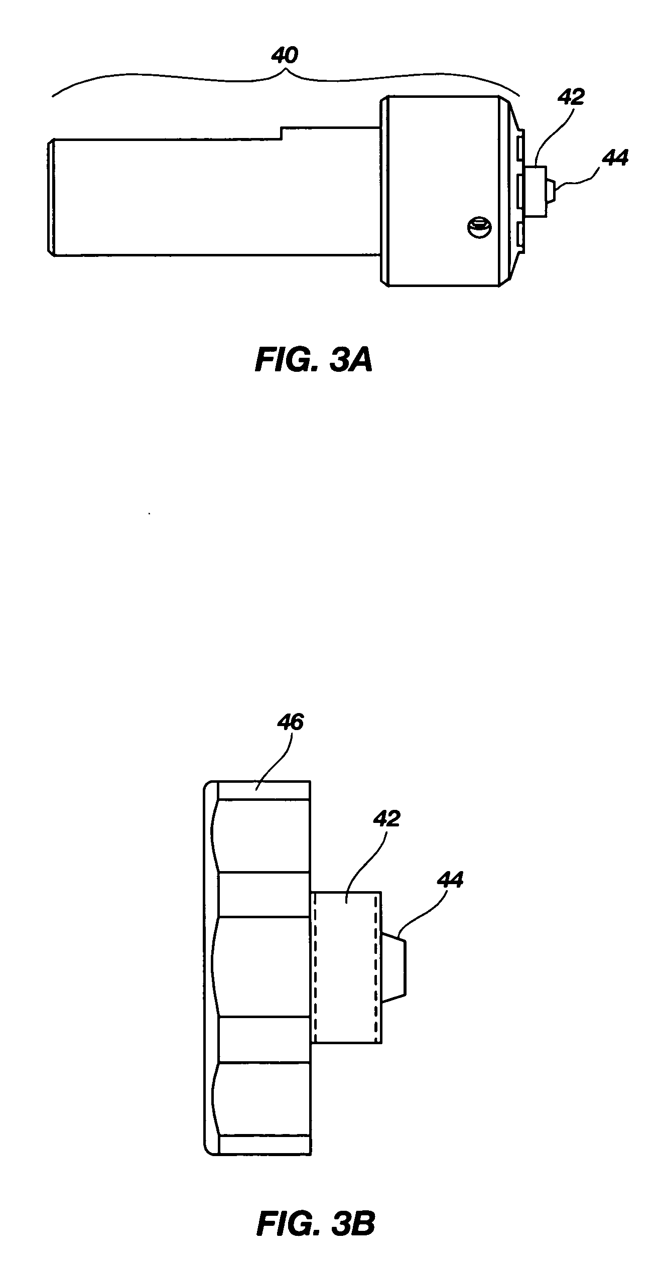
[0032] In a preferred embodiment, the present invention is a tool for friction stir spot welding of high melting temperature materials, wherein the tool geometry includes a short pin and broad shoulder to enhance mixing of high temperature materials, and wherein the tool includes a superabrasive coating to thereby enable FSSW of high melting temperature materials.

Problems solved by technology

There are many drawbacks to RSW technology.
These drawbacks include high energy costs, brittle joints that lead to cracking at the location of the weld, hazardous fumes that are emitted, low joint strength, susceptibility to corrosion, solidification defects, lack of repeatability due to probe wear at the electrode joint, and the difficulty of inspecting the quality of the joint.
However, the automotive industry continues to struggle with RSW to reliably manufacture cars.
Accordingly, the US government requires that cars produced for the consumer undergo destructive testing to determine RSW quality.
Generally, one car body from each line is destructively tested each month from each manufacturer.
However, manufacturers typically do significant destructive testing on their own by performing the test on a vehicle as often as each shift to make sure vehicle crashworthiness is maintained.
This destructive inspection process is typically used because of the unreliable nature of RSW.
Some of these steels are far more difficult to RSW.
Some of the steels cannot be welded at all using RSW.
Furthermore, the AHSS pose far more process control issues than existing steels made in today's vehicles.
For example, one process control issue is load.
Another issue is that of the gap between the parts to be welded.
The parts need to be flush, or the strength of the weld may be compromised.
Another issue is the amount of electricity needed to perform RSW on AHSS.
Although a substantial weight savings can be obtained if these advanced steels can be used in vehicle construction, there has been very little success because of the joining problems associated with RSW.
However, because of existing FSSW tool limitations, aluminum (a low melting temperature alloy) has been the only material that can be joined by the RSW process.
Unfortunately, aluminum cannot be used for structural components in a vehicle such as for the frame or body, and therefore its use is limited not only in automotive applications, but for other applications as well.
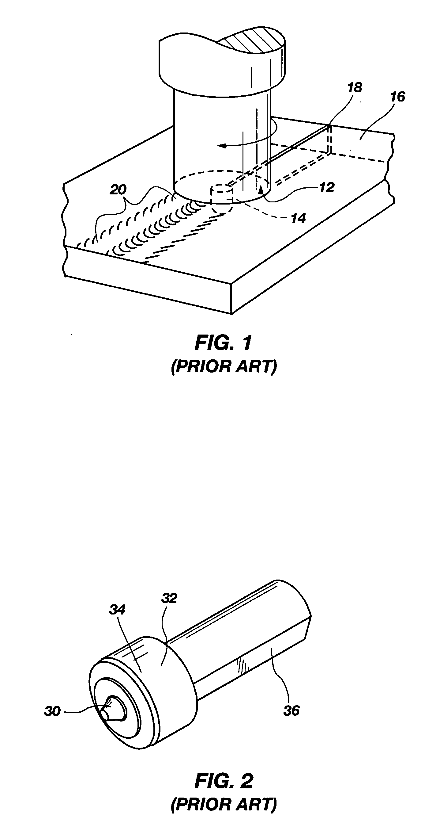
Force is exerted to urge the spindle and the workpieces together and frictional heating caused by the interaction between the spindle and the workpieces results in plasticization of the material on either side of the joint.
Some of these materials are non-fusion weldable, or just difficult to weld at all.
The design shown in FIG. 2 is in part driven by the limited sizes that can be produced by sintering, hipping, and other high pressure equipment capabilities.

Method used


Image

  • Tool geometries for friction stir spot welding of high melting temperature alloys
  • Tool geometries for friction stir spot welding of high melting temperature alloys
  • Tool geometries for friction stir spot welding of high melting temperature alloys

Examples


Embodiment Construction

[0045] Reference will now be made to the drawings in which the various elements of the present invention will be given numerical designations and in which the invention will be discussed so as to enable one skilled in the art to make and use the invention. It is to be understood that the following description is only exemplary of the principles of the present invention, and should not be viewed as narrowing the claims which follow.

[0046] From recent developments with tool materials such as Polycrystalline Cubic Boron Nitride (PCBN) and other materials which have a higher melting point than those materials being joined, friction stir welding (FSW) of high melting temperature materials has become a reality. However, in recent FSSW tests, it has become apparent that the tool geometries used for FSSW are going to be different from those used in FSW. Changes in tool geometry include, but should not be considered limited to, pin length, modifying the pin length to shoulder width ratio, t...


PUM

PropertyMeasurementUnit
Travel speedsaaaaaaaaaa
cycle timeaaaaaaaaaa

Abstract

A tool for friction stir spot welding of high melting temperature materials, wherein the tool geometry includes a short pin and broad shoulder to enhance mixing of high temperature materials, and wherein the tool includes a superabrasive coating to thereby enable FSSW of high melting temperature materials.

Description

CROSS REFERENCE TO RELATED APPLICATIONS [0001] This document claims priority to and incorporates by reference all of the subject matter included in the provisional patent application having docket number 3252.SMII.PR, with Ser. No. 60 / 653,158 and filed on Feb. 15, 2005, and the subject matter in Continuation patent applications having docket number 1219.BYU.CN with Ser. No. 10 / 705,668 and filed on Nov. 10, 2003, and docket number 1219.BYU.CN2 with Ser. No. 10 / 705,717 and filed on Nov. 10, 2003.BACKGROUND OF THE INVENTION [0002] 1. Field Of the Invention [0003] This invention relates generally to friction stir welding. More specifically, the present invention relates to spot welding of high melting temperature alloys. [0004] 2. Description of Related Art [0005] There are many applications in a variety of industries that require spot welding. For example, the shipyard, marine, automotive, transportation, aerospace, nuclear, oil and gas and other industries all need to join together, g...

Claims


Application Information

Patent Timeline
Patent Type & Authority Applications(United States)
IPC IPC(8): B23K20/12
CPCB23K20/1255
Inventor PACKER, SCOTT M.STEEL, RUSSELL J.
Owner MAZAK CORP
Learn More