
Control apparatus and method of operating same

a control apparatus and control method technology, applied in the field of control apparatus, can solve the problems of increasing the possibility of erroneous determination, increasing the cost and the area of mounting sensors, and inability to correctly set the control apparatus into fail safe mode, so as to increase the temperature of the control apparatus

Inactive Publication Date: 2006-08-03
HITACHI LTD
View PDF3 Cites 13 Cited by
  • Summary
  • Abstract
  • Description
  • Claims
  • Application Information

AI Technical Summary

Benefits of technology

[0005] According to the present invention, an increase in the temperature of the control apparatus can be readily estimated from the ambient temperature of the control apparatus, a current value instructed by the CPU to the element mounted in the control apparatus and having a concern of heat generation, and the thermal r

Problems solved by technology

The prior art has the disadvantage of the inability to correctly set the control apparatus into the fail safe mode when the temperature sensor itself mounted in the control apparatus fails.
In this event, the requirement of a plurality of temperature sensors causes a problem of an increase in the cost and the area of mounting the sensors.
Also, as described above, from a viewpoint of the reliability of the temperature sensor itself, the employment of a plurality of sensors which are relied on determining whether or not the control apparatus should be set into the fail safe mode increases the possibility of erroneous determination due to a fault of the temperature sensors themselves.

Method used


Image

  • Control apparatus and method of operating same
  • Control apparatus and method of operating same
  • Control apparatus and method of operating same

Examples


Embodiment Construction

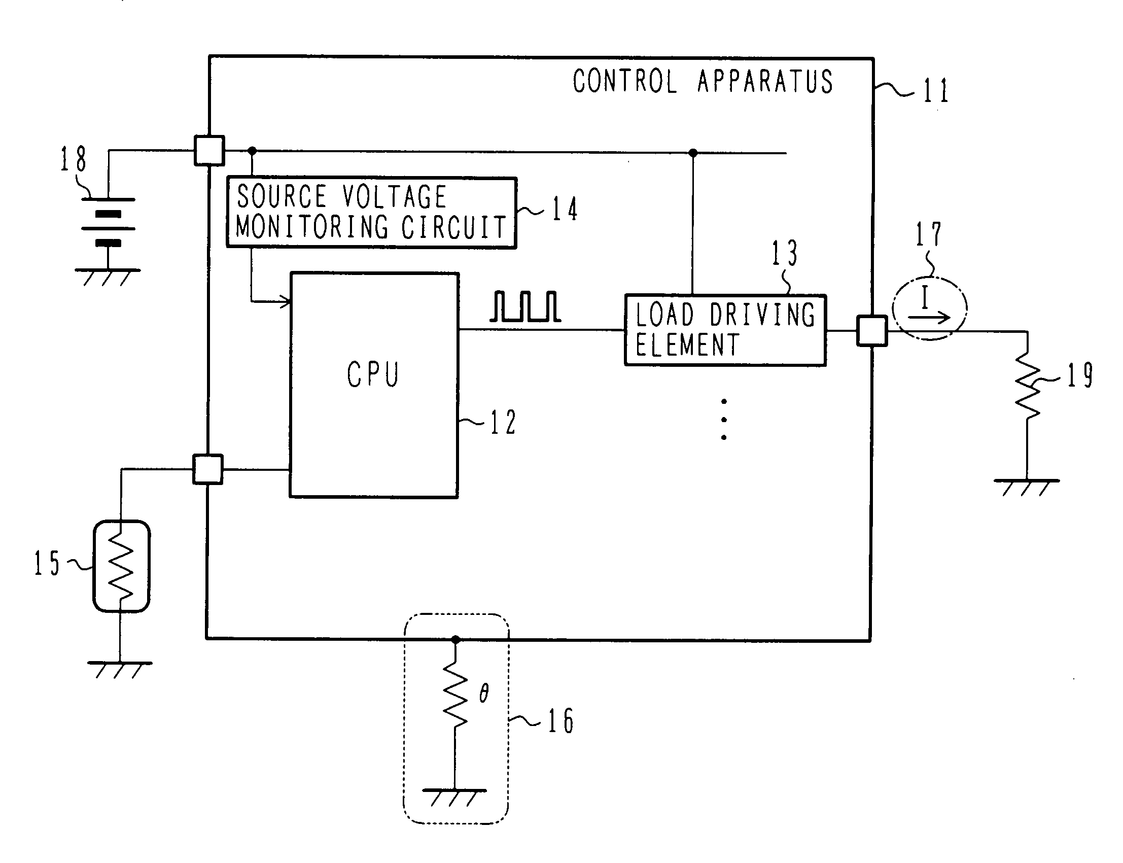
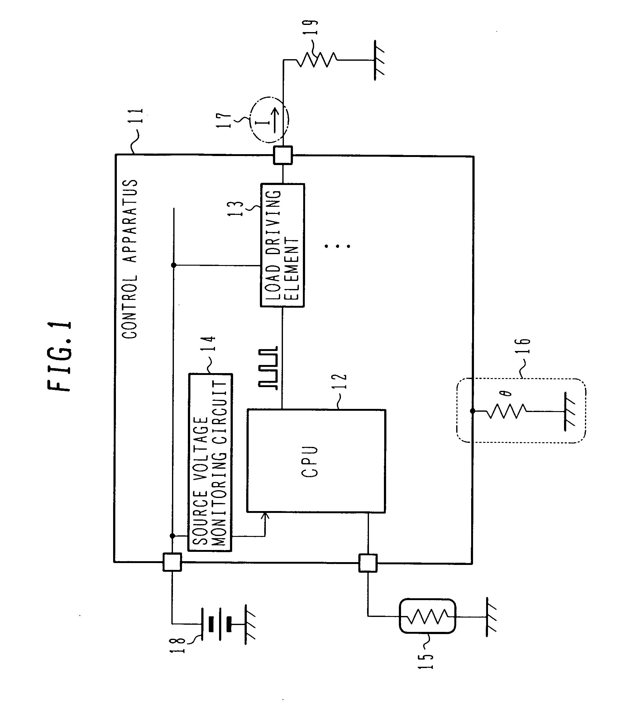
[0018] In the following, one embodiment of the present invention will be described with reference to FIG. 1.

[0019] A control apparatus 11 comprises a power supply 18 for powering the control apparatus 11, an ambient temperature sensor 15 for detecting the ambient temperature out of the control apparatus 11, a CPU 12 for capturing temperature information from the ambient temperature sensor 15 to perform operational processing based on predetermined conditions, a load driving element 13 connected to the CPU 12 for driving a load based on information processed in the CPU 12, a coil load 19 driven by the load driving element 13, and a source voltage monitoring circuit 14 for monitoring a source voltage supplied to the control apparatus 11. The control apparatus 11 is characterized by previously having the knowledge of the thermal resistance θ [° C. / W]16 of the control apparatus 11. Here, the control apparatus 11 may control, for example, an internal combustion engine.

[0020] Referring ...


PUM


Abstract

In a conventional control apparatus, the control apparatus cannot be correctly set into a fail safe mode upon failure of a temperature sensor itself mounted in the control apparatus. Also, when the control apparatus has a plurality of elements having a concern of heat generation, a plurality of temperature sensors are required corresponding to the elements having a concern of heat generation. The requirement of the plurality of temperature sensors causes an increase in the cost and mounting area. The present invention measures an instructed current value from a CPU to an element mounted in a control apparatus and having a concern of heat generation (typically, a current control element), calculates power consumption from the measured current value and a monitored source voltage, and predicts a temperature rise of the control apparatus by multiplying the power consumption by a thermal resistance parameter of the control apparatus. The control apparatus can be set into a fail safe mode for protection when it is estimated that the control apparatus could be heated beyond an upper limit of a guaranteed operation temperature range defined therefore.

Description

BACKGROUND OF THE INVENTION [0001] The present invention relates to a control apparatus and a method of operating the same, and more particularly, to techniques for setting the control apparatus itself into a fail safe mode when the control apparatus is likely to operate out of a guaranteed operation temperature range thereof due to the control apparatus itself heated by a failed element contained therein, or due to an increase in the ambient temperature due to a fault in an associated system. [0002] In the prior art, Japanese Patent No. 3371382, for example, discloses monitoring a control apparatus for the temperature by a temperature sensor mounted in the control apparatus, and setting the control apparatus into a fail safe mode when the monitored temperature satisfies a predetermined condition. SUMMARY OF THE INVENTION [0003] The prior art has the disadvantage of the inability to correctly set the control apparatus into the fail safe mode when the temperature sensor itself mounte...

Claims


Application Information

Patent Timeline
IPC IPC(8): H04N7/00G05B9/02
CPCG06F1/206G06F11/0796Y02B60/1275Y02D10/00
Inventor NAGATA, YASUHIKOTANABE, ITARU
Owner HITACHI LTD
Learn More