
Computer system performance monitoring using transaction latency data

a technology of transaction latency and computer system, applied in the field of system and method of monitoring the performance of computer systems, can solve the problems of complex arm api architecture, data speed mismatch, storage and hard disk access delay, etc., and achieves low cost, low cost, and high scalable

Inactive Publication Date: 2006-07-27
GOLDMAN SACHS & CO LLC
View PDF8 Cites 17 Cited by
  • Summary
  • Abstract
  • Description
  • Claims
  • Application Information

AI Technical Summary

Benefits of technology

This approach simplifies the design and implementation, reduces operational inefficiencies, and provides precise latency metrics and statistics, enabling effective monitoring of complex systems, facilitating capacity estimation, performance assessment, and system optimization.

Problems solved by technology

Other contributors to latency include processing / calculation delays, mismatches in data speed between the microprocessor and input / output (I / O) devices and inadequate data buffer, propagation (the time it takes for a packet to travel between one place and another); transmission medium (optical fiber, wireless, or some other medium); packet size; router and other processing (each gateway node takes time to examine and possibly change the header in a packet); and other computer and storage delays (e.g., within local area networks (LANS) or similar networks at each end of the journey, a packet may be subject to storage and hard disk access delays at intermediate devices such as switch and bridge).
system. Such an arrangement complicates the ARM API architecture and adds additional processing and storage burdens and other operational inefficiencies to the computer system whose latency characteristics the ARM API is intended to
monitor. Moreover, the ARM API can only provide for the measurement of nested transactions that are client-server in nature, i.e., with a parent-child rela
Accordingly, like those technologies, it does not permit performance evaluation of a computer system comprised of a plurality of cooperating business units and / or processes.
Codifying these items complicates the task.
That is, individually defining all of these events and transactions in software code in order to produce a complete set of transaction generation rules amounts to a potentially vast amount of preliminary preparation activity that must be performed before the monitoring system may be placed into operation.
The technique should be uncomplicated in design and implementation, minimally invasive, and highly scalable in order to accommodate potentially large volumes and frequencies of information flow through vast computer systems and networks.

Method used


Image

  • Computer system performance monitoring using transaction latency data
  • Computer system performance monitoring using transaction latency data
  • Computer system performance monitoring using transaction latency data

Examples


Embodiment Construction

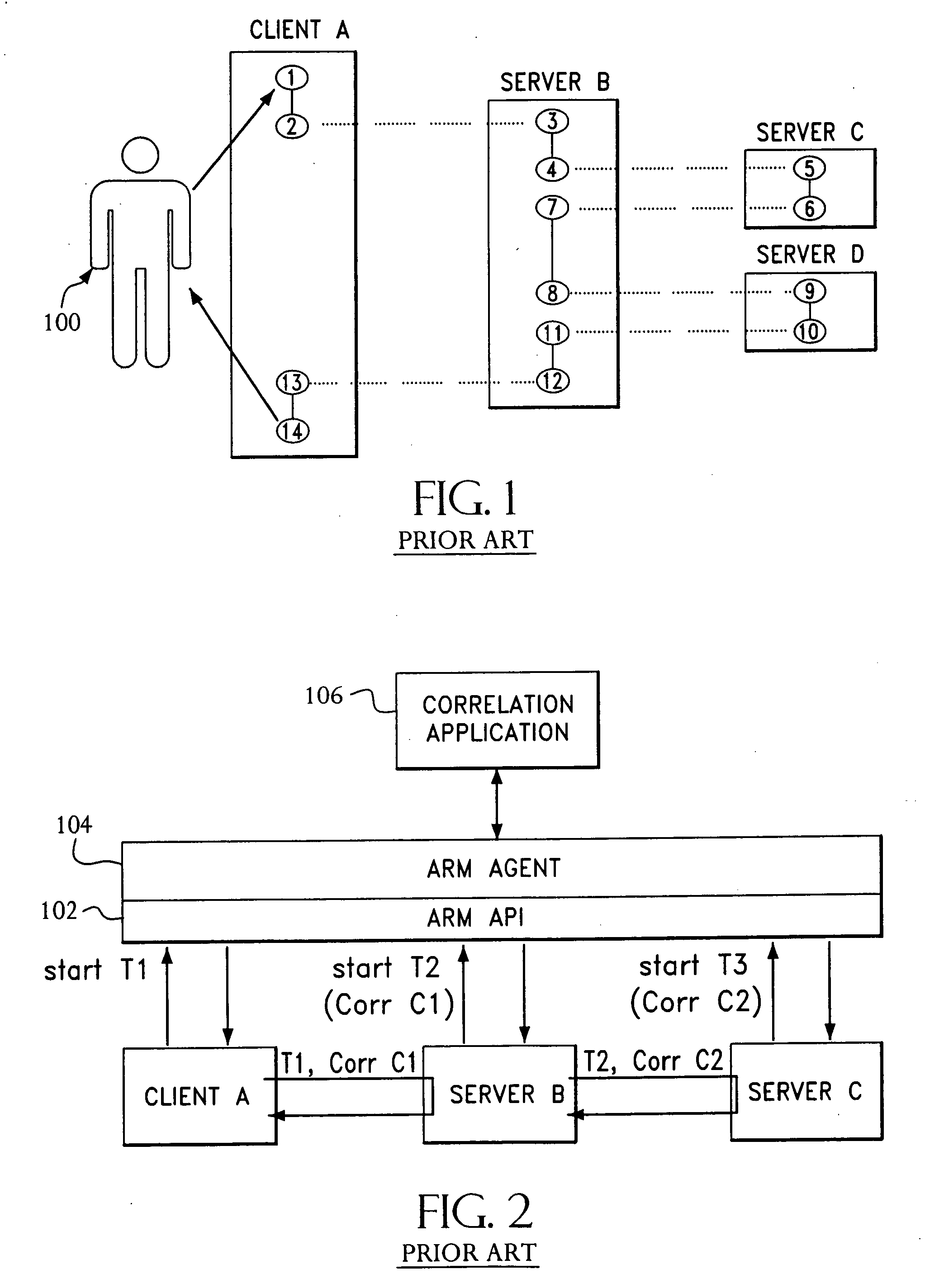
[0030] Referring to FIG. 1, there is shown a client-server computer system topology whose transactional latency may be measured by presently available IT performance optimization tools. In FIG. 1, Points 1 to 14 represent the flow of business or other transactional information through multiple transactions on multiple computers respectively named CLIENT A, SERVER B, SERVER C and SERVER D. The client-server topology represented in FIG. 1 is a nested parent-child type of topology wherein completed transaction 1 / 14 is comprised of a number of smaller nested transactions or subtransactions. Transaction 1 / 14 typically includes an initial transactional request made by user 100 (step 1) to a suitable computer input / output (I / O) device which culminates in the provision of the requested information from the I / O device to the user (step 14). Transaction 1 / 14 represents a transaction that is the parent of transaction 2 / 13, i.e., 2 / 13 is nested within 1 / 14. Transaction 2 / 13, in turn, is the par...


PUM


Abstract

Computer systems may be instrumented using a minimally invasive API that allows the execution time of every task in an application to be measured and transactional information to be tagged to the measurement or timing data. Preferably, the measurement data is also associated with related measurement data from other components or systems of the same business entity in order to give precise latency data and statistics for transactions that involve more then one segment of a business' operations.

Description

CROSS-REFERENCE TO RELATED APPLICATION [0001] This application is a Continuation of U.S. patent application Ser. No. 09 / 896,854 filed Jun. 29, 2001.FIELD OF THE INVENTION [0002] The present invention relates in general to systems and methods for monitoring the performance of computer systems and, in particular, to computer system performance monitoring using transaction latency data. BACKGROUND OF THE INVENTION [0003] Measurement and management of computer systems performance is becoming increasingly important in businesses and industries that rely heavily on information technology (IT). The financial services industry, for example, is comprised of investment houses, banks, stock exchanges, brokers, and others who conduct countless computerized transactions on a daily basis and whose capital investments in technology may be tremendous. It is imperative, therefore, that participants in this or other information-dependent industries possess not only high-powered computer systems capab...

Claims


Application Information

Patent Timeline
Patent Type & Authority Applications(United States)
IPC IPC(8): G06F9/46G06F9/00G06F11/34
CPCG06F11/3419G06F11/3452G06F11/3495G06F2201/86G06F2201/87
Inventor DEVERILL, IAN J.HAMMAD, SAFE E.HASSAN, ALEX D.FINNERTY, WARREN P.
Owner GOLDMAN SACHS & CO LLC
Learn More