
Transparent pane with radar-reflecting properties

a technology of radar reflection and transparent pane, which is applied in the field of pane, can solve the problems of deteriorating stealth properties, affecting the vehicle in combat situations, and getting very high reflectance, and achieves the effects of not reducing the reflection of the pane, preventing only minimal transparency, and high scratch resistan

Inactive Publication Date: 2006-07-27
TOTALFORSVARETAB FORSKNINGSINSTITUT FOI
View PDF33 Cites 6 Cited by
  • Summary
  • Abstract
  • Description
  • Claims
  • Application Information

AI Technical Summary

Benefits of technology

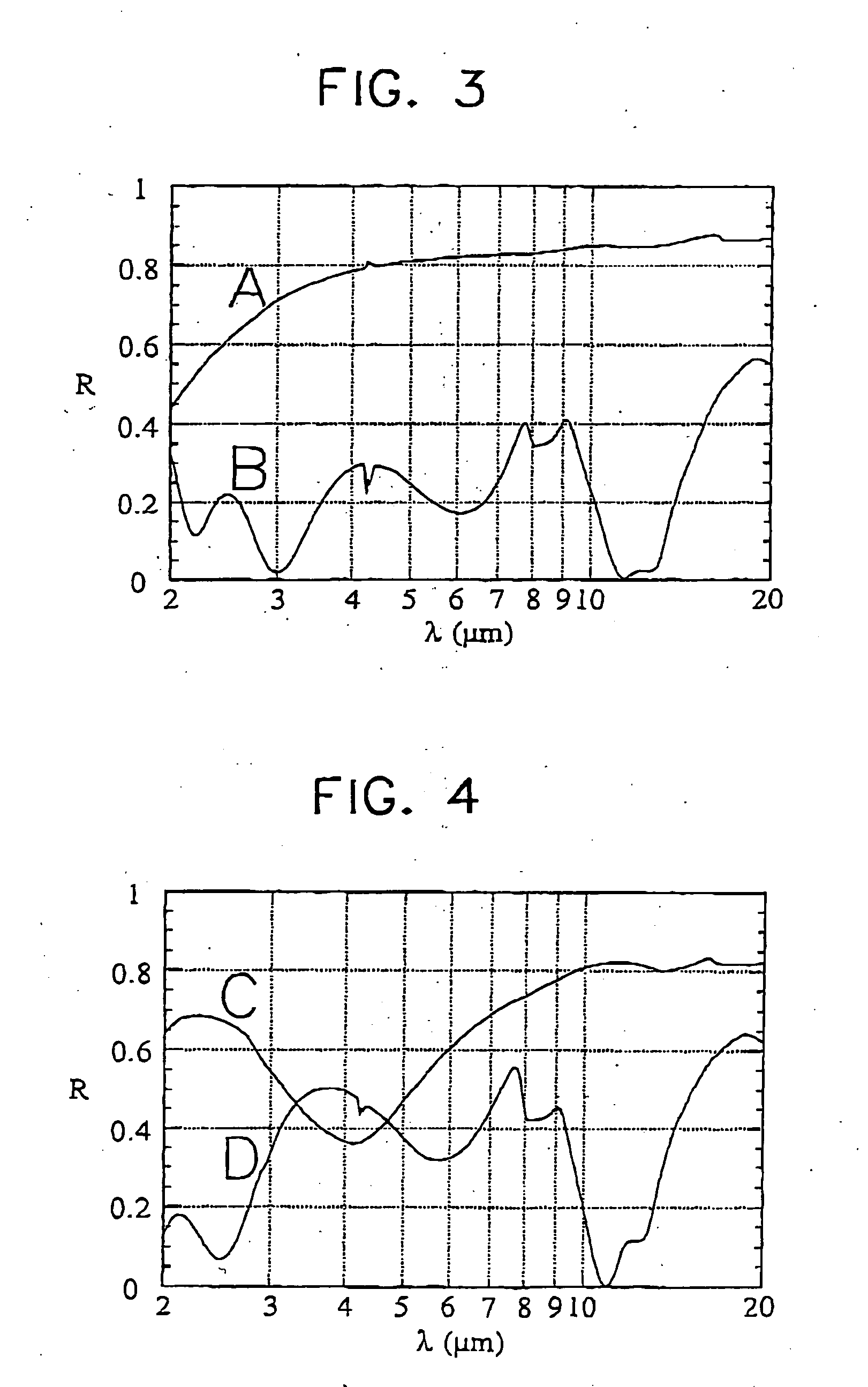
[0021] According to the preferred embodiment, use is made of coatings of undoped tin oxide and oxidised silicon nitride, which are each active in a separate IR window. The emittance in these windows has been increased to about 0.8, i.e. to a value which approximately corresponds to the value of those parts of the vehicle that surround the pane. On the IR instrument of t

Problems solved by technology

If the beams are also reflected by corner reflectors, which are often present in the interior, a considerable part of the beams is reflected back, resulting in deteriorated stealth properties.
An outer face which is highly reflective for radar has the drawback that it can get very high reflectance also for a second radiation used by the enemy.
Since recognition is the basis for an enemy's choice of a successful mode of combating, involving inter alia the choice of suitable tactics and weapons, the existence of these differently coloured fields will be highly detrimental to the vehicle in a combat situation.

Method used


Image

  • Transparent pane with radar-reflecting properties
  • Transparent pane with radar-reflecting properties
  • Transparent pane with radar-reflecting properties

Examples


embodiment

PREFERRED EMBODIMENT

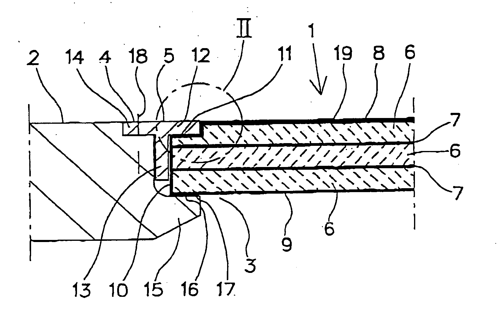
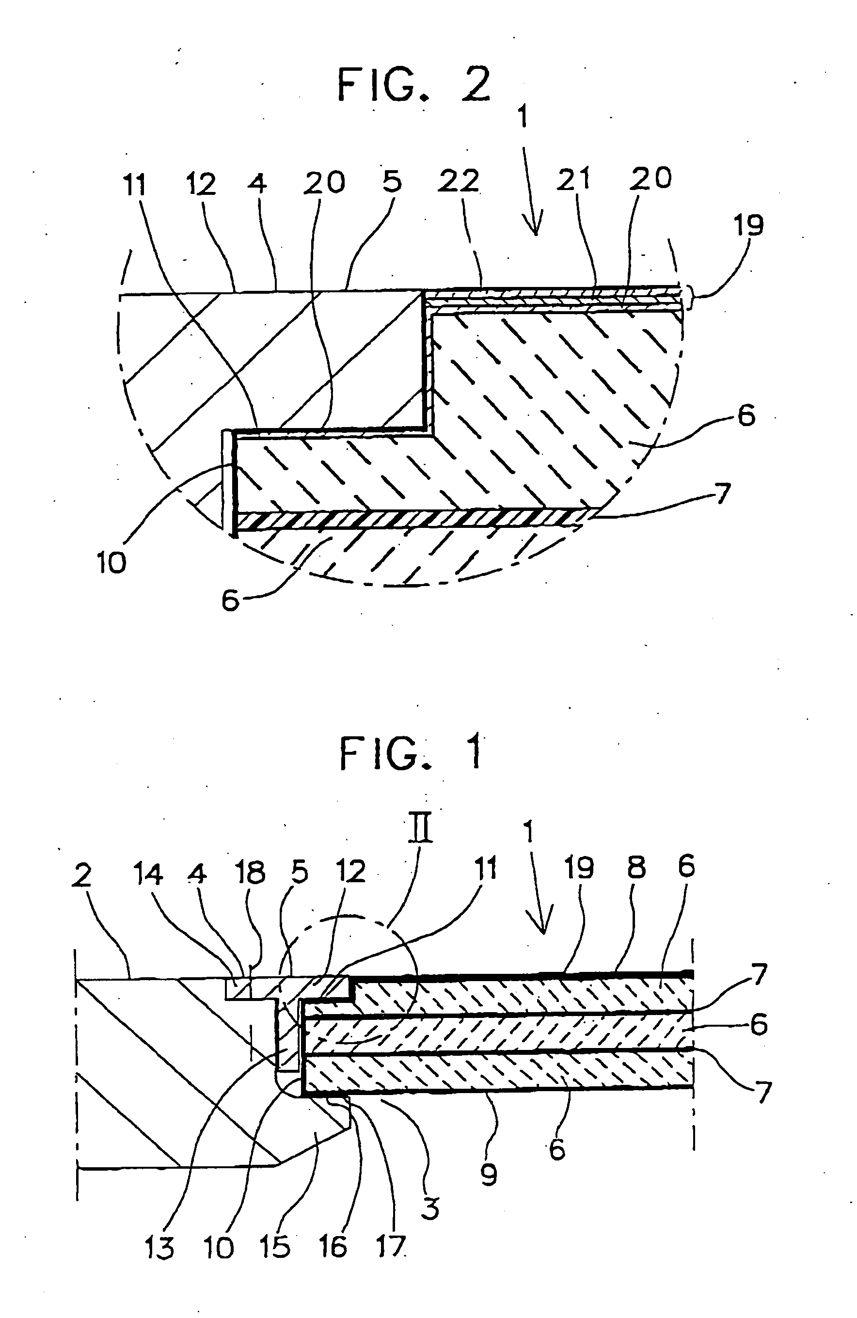
[0026]FIG. 1 shows a visual pane 1 according to the invention for a naval vessel. The visual pane is inserted in a wall 2 of a superstructure belonging to the hull of the vessel to be one of the visual panes of the navigation bridge. The visual pane is kept in place in an opening 3, which is formed in the wall 2 and which of course is a through opening, by means of a mounting frame 4 of metal. The mounting frame is made up of T-shaped sections welded together at the corners so as to obtain a flat exterior surface 5.

[0027] The visual pane consists of a laminate comprising according to prior-art technique a number of sheets 6 of toughened glass and intermediate layers 7 of polymer, preferably polyvinyl butyral. With a total thickness of about 50 mm, the pane provides, strengthened by the reinforcing properties of the polymer layers, a defensive capability which can prevent splinters from penetrating into the vessel. The visual pane has an outer face 8 and an inner...


PUM

PropertyMeasurementUnit
Lengthaaaaaaaaaa
Lengthaaaaaaaaaa
Lengthaaaaaaaaaa

Abstract

The panes (1) of a naval vessel or military vehicle are often coated with a radar-reflecting layer (20) for reduction of the radar signature of the vessel / vehicle. At the same time this layer increases an enemy's possibility of recognising the vessel in passive IR reconnaissance since the layer increases the reflectance also for IR radiation to a considerable extent. As a result, the intensity of IR radiation that an enemy receives from the panes is much lower than that from the rest of the vessel, which with signal processing can be used to increase the possibility of recognising the vessel. According to the invention, it is suggested that the panes (1) on the outer face (8) also have a second layer (21, 22) to increase emittance especially within the IR range 2-20 μm which is normally used for reconnaissance and the like. This second layer (21, 22) comprises especially two coatings, one of which is active in the IR range 3-5 μm and the second in the IR range 7-14 μm. The first coating (21) is suggested to comprise tin dioxide and the second coating (22) oxidised silicon nitride.

Description

FIELD OF THE INVENTION [0001] The invention relates to a pane according to the preamble to claim 1. The pane is intended for use mainly as a visual pane in a military vehicle or vessel, for instance a combat vehicle or a marine vessel. To reduce, for instance, back reflection to a radar transmitter, the pane which is preferably made of glass is arranged with an outer face reflecting radar beams. To this end, the pane is usually coated with a layer of metal or metal oxide. BACKGROUND ART [0002] Vehicles or vessels of different kinds are provided with panes to make it possible for the crew to look out from the interior of the vehicle, to cover sights, searchlights etc. The panes, which are transparent to the useful radiation used for the purpose, which can be IR or UV radiation but preferably light visible to the eye, are usually made of glass. When IR radiation is used, they are made of e.g. germanium. If the panes are used in combat vehicles, they should provide good defensive capab...

Claims


Application Information

Patent Timeline
IPC IPC(8): F21V9/04G02B5/20G02B5/08F21V9/06B32B17/10B63B19/00B63G13/02C03C17/34F41H3/00
CPCB32B17/10036B32B17/10761B63B19/00B63B2019/0038B63G13/02B63G2013/027C03C17/3411C03C17/3435C03C17/3452C03C2217/734F41H3/00F41H5/263
Inventor GEORGSON, MIKAELSTAAF, ORJAN
Owner TOTALFORSVARETAB FORSKNINGSINSTITUT FOI
Learn More