Single sensor ring laser gyroscope
a laser gyroscope and single sensor technology, applied in the direction of speed measurement using gyroscopic effects, instruments, surveying and navigation, etc., can solve the problems of low readout signal (power), production cycle time, performance degradation,
- Summary
- Abstract
- Description
- Claims
- Application Information
AI Technical Summary
Benefits of technology
Problems solved by technology
Method used
Image
Examples
Embodiment Construction
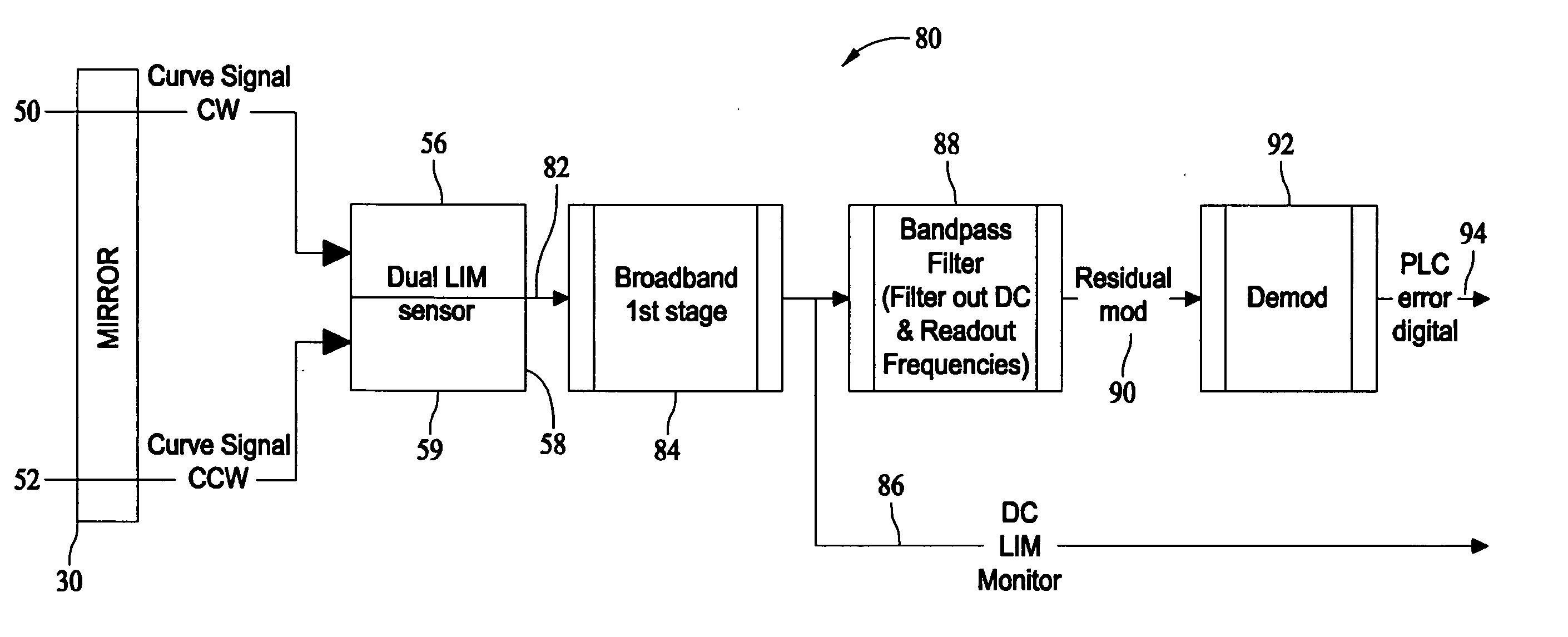
[0028]FIG. 1 is a diagram illustrating optical components and an optical path for transmitted beams within a known ring laser gyroscope 10. Ring laser gyroscope 10 includes a substantially triangular laser block 12 that provides a ring laser cavity 14 containing lasing gas. Laser block 12 includes block surfaces 16, 18, and 20 between which is an optical laser path with vertices 22, 24, and 26 at respective block surfaces 16, 18, and 20. Mirror assemblies 28, 30, and 32 are mounted to block surfaces 16, 18, and 20, respectively. Ring laser cavity 14 is filled with a lasing gas that is ignited or excited by a sufficient voltage between cathode 34 and each of anodes 36 and 38. In turn, a pair of counter-propagating laser beams travel along the optical laser path within laser cavity 14. One or more of mirror assemblies 28, 30, and 32 are transmissive, which allows a portion of the counter-propagating laser beams to pass through the mirror and onto sensors as further described below.
[0...
PUM
 Abstract
Description
Claims
Application Information
 - R&D
- Intellectual Property
- Life Sciences
- Materials
- Tech Scout
- Unparalleled Data Quality
- Higher Quality Content
- 60% Fewer Hallucinations
Browse by: Latest US Patents, China's latest patents, Technical Efficacy Thesaurus, Application Domain, Technology Topic, Popular Technical Reports.
© 2025 PatSnap. All rights reserved.Legal|Privacy policy|Modern Slavery Act Transparency Statement|Sitemap|About US| Contact US: help@patsnap.com


