
Light source, and optical coherence tomography module

Active Publication Date: 2012-02-02
EXALOS
View PDF8 Cites 92 Cited by
  • Summary
  • Abstract
  • Description
  • Claims
  • Application Information

AI Technical Summary

Benefits of technology

[0019]The approach brings about advantages in terms of compactness, handling, manufacturing cost and calibration effort by the user. In accordance with preferred embodiments, the devices of the package have a common thermoelectric cooler that is in contact with a mount on which a plurality of the components within the module casing are arranged. This brings about further advantages in terms of stability and reproducibility as well as being advantageous in terms of manufacturing complexity.
[0093]a DC signal offset compensation: Such a DC signal offset compensation may be based on the principle of heterodyne balanced detection. It may eliminate the effect of primary light source intensity variations, that for example may arise periodically with the sweeping frequency (if the produced radiation intensity has some wavelength dependence) or slowly as a reaction to changing parameters such as a temperature change etc. For example, the two outputs of the beam splitter / combiner may be used and directed at two detectors, and the measured intensities at these detectors are subtracted from each other. Since the interference signal occurs 180° degrees out of phase at the two detectors, subtracting the two signals adds the heterodyne interference signal but subtracts excess noise.

Problems solved by technology

The Fabry-Perot MEMS device is essentially a linear transducer that has speed limitations and is susceptible to variations in reflectivity, parallelism, flatness and filter cavity thickness over the tuning bandwidth.
Integration of these elements, however, is difficult to manufacture and has yet to be realized.
However, it would not be good to take a swept source that has a too long coherence length because then any kind of reflective object within the imaging range will cause unwanted interference signals.
Single mode operation would not guarantee that the coherence length does not exceed a certain maximum acceptable value.
Also, a too long cavity length makes the wavelength tuning slow limiting the sweep rate.

Method used


Image

  • Light source, and optical coherence tomography module
  • Light source, and optical coherence tomography module
  • Light source, and optical coherence tomography module

Examples


Embodiment Construction

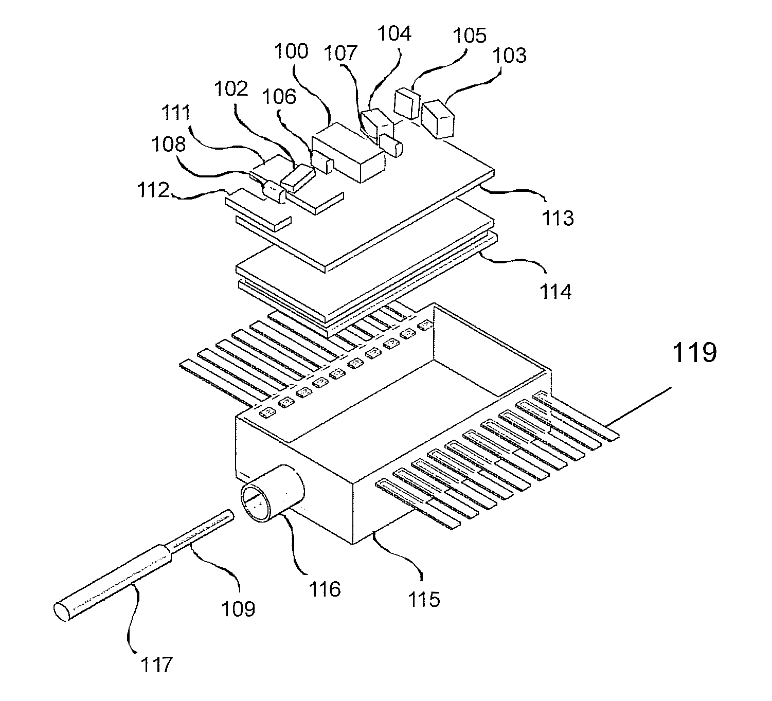
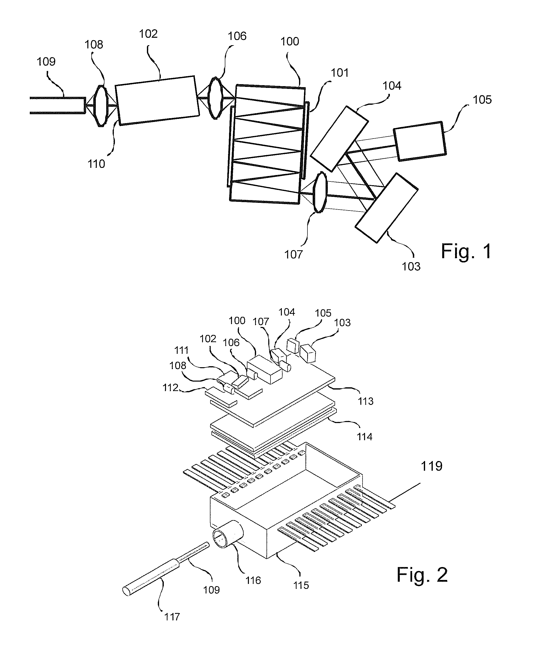
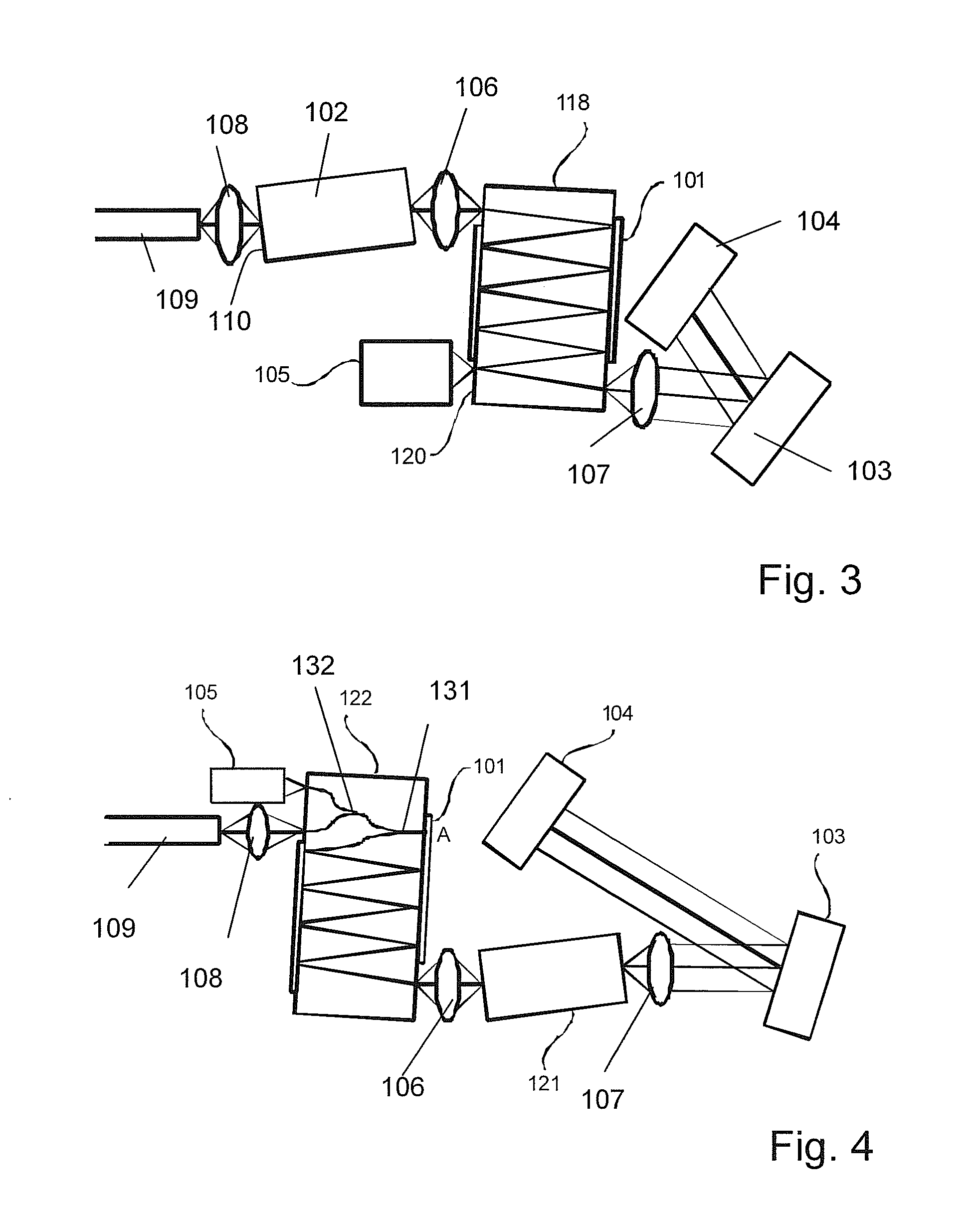
[0114]A first embodiment of the invention is an optical arrangement as shown in FIG. 1. In this embodiment, the optical arrangement comprises an optical retarding device 100 having reflective coatings 101 at opposing facets, an optical gain block 102, scanning MEMS mirror 103, diffraction grating 104, monitor photodiode 105, a gain block coupling lens 106 and a lens 107 that may be collimating or imaging the beam.

[0115]In this embodiment and in other depicted embodiments, the resonator design ins based on the so-called Littrow configuration, where the diffraction grating acts as a resonator mirror. However, the invention, pertaining to all embodiments, is not restricted to such configuration. The skilled person will know other resonator configurations of tunable resonators for externa-cavity diode lasers. An other known configuration is the so-called Littman-Metcalf configuration where a separate mirror (that may be the movable device), onto which diffracted radiation is directed, i...


PUM


Abstract

A swept wavelength light source is provided, the light source includes a semiconductor gain device operable to provide amplification, an optical retarding device, the retarding device having a block of material, a beam path with a well-defined beam path length being defined for light within the block of material produced by the gain device, a wavelength selector, and the gain device, the retarding device and wavelength selector being mutually arranged on the base so that a resonator is established for light portions emitted by the gain device and selected by wavelength selector; this does not exclude the presence of further elements contributing to the resonator, such as additional mirrors (including resonator end mirrors), lenses, polarization selective elements, other passive optical components, etc.; wherein the beam path in the retarding device is a part of a beam path of the resonator.

Description

FIELD OF THE INVENTION[0001]The invention is in the field of light sources, i.e. of sources of electromagnetic radiation in the infrared, visible, and ultraviolet part of the electromagnetic radiation spectrum. More concretely, the invention concerns a light source, an optical coherence tomography apparatus, and an optical coherence tomography module.BACKGROUND OF THE INVENTION[0002]Optical Coherence Tomography (OCT) is an emerging technique for sub-surface imaging with medical, biological and other applications. OCT is the optical analog of ultrasound but takes advantage of the shorter wavelengths of light to achieve higher resolution images. Potentially the wavelength ranges of interest lie within the visible to near infrared regions of the spectrum from 400-2000 nm. Currently, there are four wavelength ranges of interest in OCT centered around 850 nm, 1050 nm, 1300 nm and 1550 nm. OCT systems comprise (1) a broadband light source, (2) an arrangement of optical components for dire...

Claims


Application Information

Patent Timeline
IPC IPC(8): G01B9/02F21V19/00G02B6/04F21V9/00
CPCG01N21/4795H01S5/02216H01S5/02248H01S5/02284H01S5/02415H01S5/02438H01S5/06H01S5/141H01S5/143H01S3/0813G01B9/02004G01B9/02091H01S5/0683H01S5/02325H01S5/02251
Inventor LEWANDOWSKI, JANDUELK, MARCUSVELEZ, CHRISTIAN
Owner EXALOS
Learn More