
Method for determining and compensating the scale factor error cause by a wavelength change in a gps-based inertial navigation system

a technology of inertial navigation and wavelength change, applied in wave based measurement systems, navigation instruments, instruments, etc., can solve the problems of scale factor error resulting from a change in the wavelength of light sources, scale factor can no longer be estimated or determined satisfactorily, scale factor error will become evident, etc., to achieve the effect of improving scale factor accuracy

Inactive Publication Date: 2006-07-06
LITEF
View PDF6 Cites 14 Cited by
  • Summary
  • Abstract
  • Description
  • Claims
  • Application Information

AI Technical Summary

Benefits of technology

[0009] It is therefore an object of the invention to provide a method for improving scale factor accuracy, particularly for a GPS-supported inertial attitude and heading reference system equipped with a multiple axis fiber-optic gyroscope that is fed from a common light source.

Problems solved by technology

However as mentioned above, the determination of sensor errors with the aid of external assistance and Kalman filter techniques, is dependent upon a specific amount of motion dynamics of the vehicle (e.g. an aircraft) as error mechanisms of the inertial sensors can only be stimulated in this way.
On the other hand, GPS reception is lost during very major attitude angle changes (e.g. aircraft engaged in aerobatics) when the GPS antenna can no longer receive satellite signals.
As a result, the scale factor can then no longer be estimated or determined satisfactorily.
Furthermore, any increase in scale factor error resulting from a change in the wavelength of the light source will become evident only after the systems have been in use for a relatively long time.
The reduction in accuracy in attitude / heading reference systems generally remains unknown as the system error is largely suppressed by vertical and magnetic sensor assistance, and has therefore been found to be relatively insignificant.

Method used


Image

  • Method for determining and compensating the scale factor error cause by a wavelength change in a gps-based inertial navigation system
  • Method for determining and compensating the scale factor error cause by a wavelength change in a gps-based inertial navigation system
  • Method for determining and compensating the scale factor error cause by a wavelength change in a gps-based inertial navigation system

Examples


Embodiment Construction

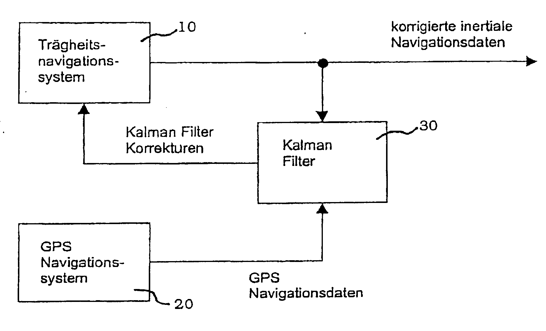
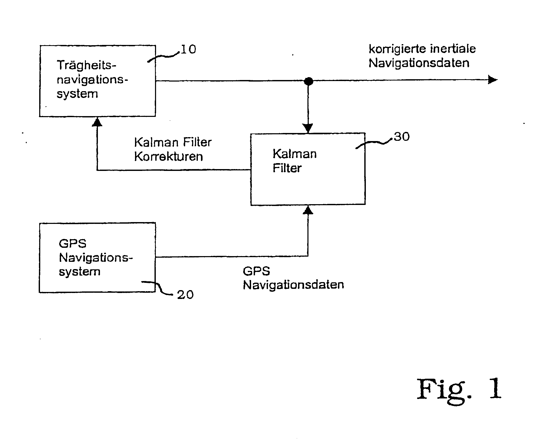
[0014]FIG. 1 is a functional block diagram of an inertial navigation system, supported by GPS data and including Kalman filter correction. The scale factor of a fiber optic gyroscope within an inertial navigation system 10 is governed predominantly by two factors. The Sagnac phase, which is produced by an external spin rate in the FOG (not illustrated), is governed by the wavelength (or frequency) of light in the glass fiber and the geometric dimensions of the fiber coil (the area enclosed by the winding). In a resetting system, the scaling of the reset (scaling: rotation angle increment / Sagnac phase) in the fiber gyro control loop governs the scale factor.

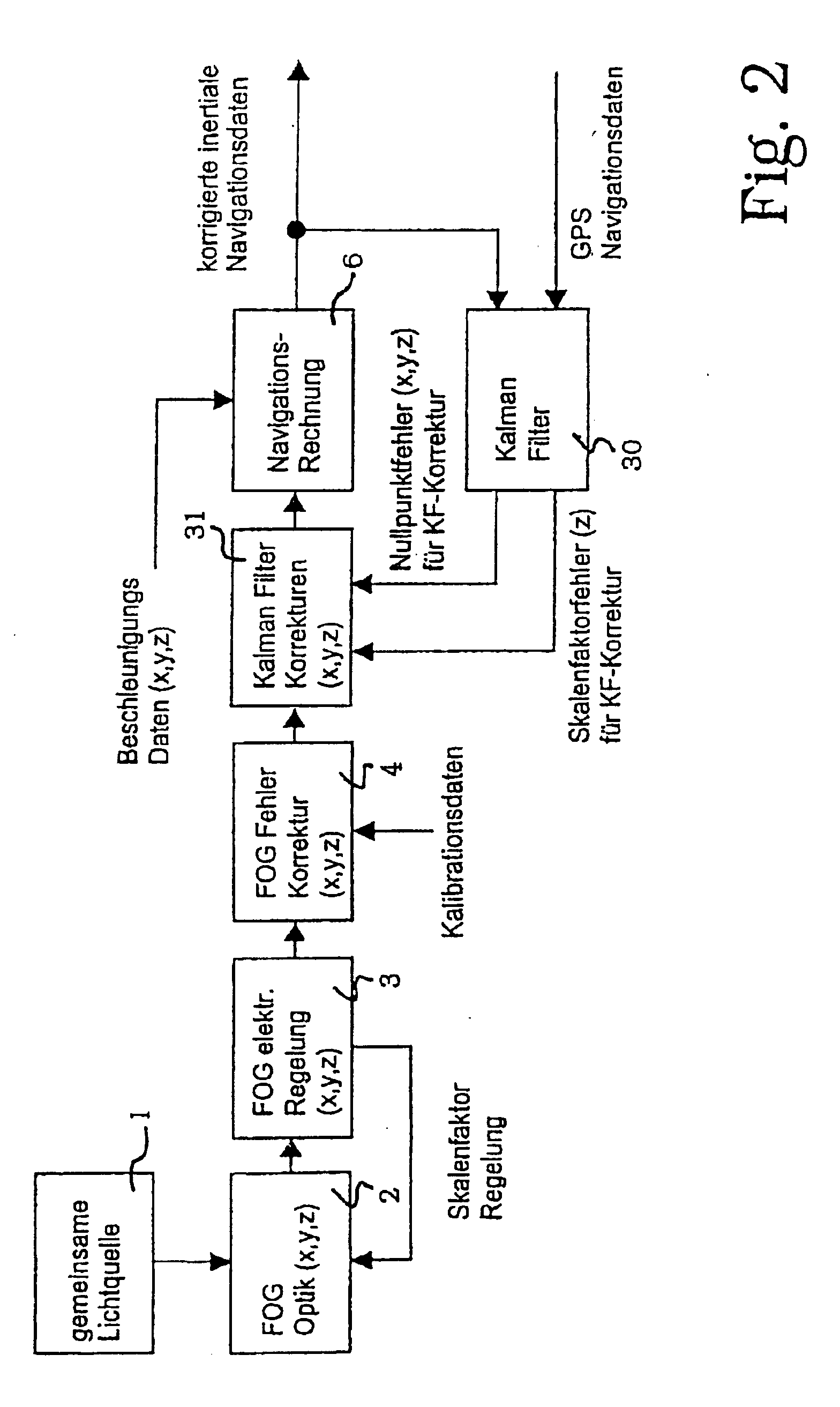
[0015]FIG. 2 is a detailed functional block diagram for illustrating error correction, scale factor correction in particular, in accordance with the method of the invention. In a multiple (e.g. three) axis FOG architecture 2 fed from a common light source 1, electrical scale factor is determined and monitored by an auxiliary cont...


PUM


Abstract

In a GPS-supported inertial attitude and heading reference system equipped with a Kalman correction filter and a multiple axis fiber optic gyroscope, the invention provides for only that scale factor error which is determined for the measurement axis (e.g. the vertical axis) with relatively fast motion dynamics to be used as the Kalman filter correction value for the scale factor error correction for all the measurement axes of the FOG to determine and compensate for the scale factor error caused by changes in the wavelength of a common light source. The scale factor error correction is used only with a long time constant.

Description

BACKGROUND [0001] 1. Field of the Invention [0002] The present invention relates to GPS-supported inertial attitude and heading reference (INS-Systems) systems having Kalman filters. More particularly, this invention pertains to a method for determination and compensation of scale factor error in such a system due to wavelength changes in multiple-axis fiber optic gyroscopes having a common light source. [0003] 2. Description of the Prior Art [0004] DE 196 51 543 C1 teaches subtraction of attitude and heading angles produced by a GPS receiver from the corresponding data supplied by an inertial sensor for iterative correction of a platform calculation by means of a Kalman filter, in a attitude and heading reference system including an inertial system that is assisted by means of a GPS receiver. Such method obtains an accurate attitude / heading reference of comparatively wide bandwidth that is independent of acceleration sensors. Correction models for GPS / INS mechanizations for attitud...

Claims


Application Information

Patent Timeline
IPC IPC(8): G01C21/28G01C19/72G01C21/16
CPCG01C19/72G01C21/165G01C21/188
Inventor KRINGS, MANFRED
Owner LITEF
Learn More