
Caching engine in a messaging system

a messaging system and cache engine technology, applied in the field of data messaging, can solve the problems of scalability and operational problems, messaging system architecture produces latency, and create performance bottlenecks

Inactive Publication Date: 2006-07-06
TERVELA INC
View PDF48 Cites 47 Cited by
  • Summary
  • Abstract
  • Description
  • Claims
  • Application Information

AI Technical Summary

Benefits of technology

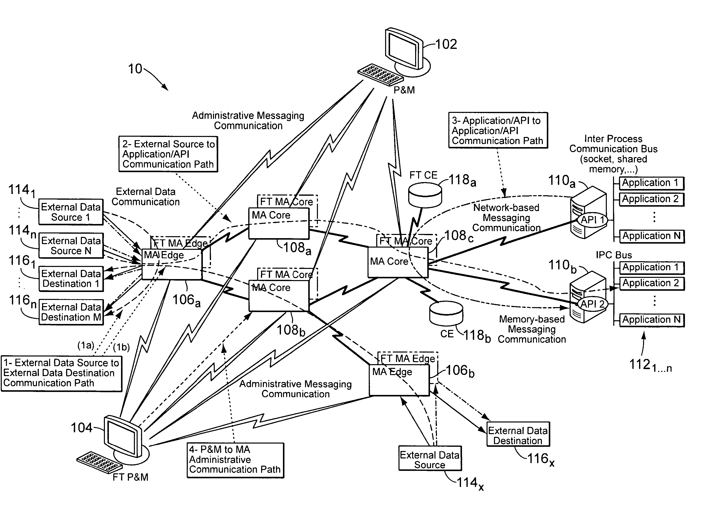
[0015] In order to support such services, the CE is designed to keep up with the forwarding rate of the MA. For example, the CE is designed with a high-throughput connection between the MA and the CE for pushing messages as fast as possible, a high-throughput and smart indexing mechanism for inserting and replaying messages from a back-end CE database, and high-throughput, persistent storage devices. One of the considerations in this design is reducing the latency of replay requests.
[0020] These caching engines can be configured and deployed as fault tolerant pairs, composed of a primary and secondary CEs, or as fault tolerant groups, composed of more than two CE nodes. If two or more CEs are logically linked to each other, they subscribe to the same data and thus maintain a unique and consistent view of the subscribed data. Note that subscription of CEs to data is topic-based, much like application programming interfaces (APIs). In the event of data loss, a CE can request a replay of the lost data to the other CE members of the fault-tolerant group. The synchronization of the data between CEs of the same fault-tolerant group is parallelized by the messaging fabric which, via the MAs, intelligently and efficiently forwards copies of the subscribed messaging traffic to all caching engine instances. As a result, this enables asynchronous data consistency for fault tolerant and disaster recovery deployments, where the data synchronization is performed and persistency is assured by the messaging fabric rather than by leveraging storage / disk mirroring or database replication technologies.

Problems solved by technology

With the hub-and-spoke system configuration, all communications are transported through the hub, often creating performance bottlenecks when processing high volumes.
Therefore, this messaging system architecture produces latency.
However, such architecture presents scalability and operational problems.
By comparison to a system with the hub-and-spoke configuration, a system with a peer-to-peer configuration creates unnecessary stress on the applications to process and filter data and is only as fast as its slowest consumer or node.
The storage operation is usually done by indexing and writing the messages to disk, which potentially creates performance bottlenecks.
Furthermore, when message volumes increase, the indexing and writing tasks can be even slower and thus, can introduces additional latency.
The challenge for such implementation is to ensure data consistency between the primary and secondary sites at all times with low latency.
The problem with such synchronous implementation is that it impacts the overall performance of the messaging layer.
However, with this approach the challenge of avoiding data loss or corruption is to maintain data consistency while the disaster is occurring.
Another challenge is to ensure ordering of data updates.
One common deficiency is that data messaging in existing architectures relies on software that resides at the application level.
This implies that the messaging infrastructure experiences OS (operating system) queuing and network I / O (input / output), which potentially create performance bottlenecks.
Another common deficiency is that existing architectures use data transport protocols statically rather than dynamically even if other protocols might be more suitable under the circumstances.
Indeed, the application programming interface (API) in existing architectures is not designed to switch between transport protocols in real time.
The limitations associated with static (fixed) configuration preclude real time dynamic network reconfiguration.
In other words, existing architectures are configured for a specific transport protocol which is not always suitable for all network data transport load conditions and therefore existing architectures are often incapable of dealing, in real-time, with changes or increased load capacity requirements.
Furthermore, when data messaging is targeted for particular recipients or groups of recipients, existing messaging architectures use routable multicast for transporting data across networks.
However, in a system set up for multicast there is a limitation on the number of multicast groups that can be used to distribute the data and, as a result, the messaging system ends up sending data to destinations which are not subscribed to it (i.e., consumers which are not subscribers).
This increases consumers' data processing load and discard rate due to data filtering.
Then, consumers that become overloaded for any reason and cannot keep up with the flow of data eventually drop incoming data and later ask for retransmissions.
Therefore, retransmissions can cause multicast storms and eventually bring the entire networked system down.
When the system is set up for unicast messaging as a way to reduce the discard rate, the messaging system may experience bandwidth saturation because of data duplication.
And, although this solves the problem of consumers filtering out non-subscribed data, unicast transmission is non-scalable and thus not adaptable to substantially large groups of consumers subscribing to a particular data or to a significant overlap in consumption patterns.
One more common deficiency of existing architectures is their slow and often high number of protocol transformations.

Method used


Image

  • Caching engine in a messaging system
  • Caching engine in a messaging system
  • Caching engine in a messaging system

Examples


Embodiment Construction

[0032] Before outlining the details of various embodiments in accordance with aspects and principles of the present invention the following is a brief explanation of some terms that may be used throughout this description. It is noted that this explanation is intended to merely clarify and give the reader an understanding of how such terms might be used, but without limiting these terms to the context in which they are used and without limiting the scope of the claims thereby.

[0033] The term “middleware” is used in the computer industry as a general term for any programming that mediates between two separate and often already existing programs. Typically, middleware programs provide messaging services so that different applications can communicate. The systematic tying together of disparate applications, often through the use of middleware, is known as enterprise application integration (EAI). In this context, however, “middleware” can be a broader term used in the context of messa...


PUM


Abstract

Message publish / subscribe systems are required to process high message volumes with reduced latency and performance bottlenecks. The end-to-end middleware architecture proposed by the present invention is designed for high-volume, low-latency messaging and with guaranteed delivery quality of service through data caching that uses a caching engine (CE) with storage and storage services. In a messaging, a messaging appliance (MA) receives and routes messages, but it first records all or a subset of the routed messages by sending a copy to the CE. Then, for a predetermined period of time, recorded messages are available for retransmission upon request by any component in the messaging system, thereby providing guaranteed-connected and guaranteed-disconnected delivery quality of service as well as partial data publication service.

Description

REFERENCE TO EARLIER-FILED APPLICATIONS [0001] This application claims the benefit and incorporates by reference U.S. Provisional Application Ser. No. 60 / 641,988, filed Jan. 6, 2005, entitled “Event Router System and Method” and U.S. Provisional Application Ser. No. 60 / 688,983, filed Jun. 8, 2005, entitled “Hybrid Feed Handlers And Latency Measurement.”[0002] This application is related to and incorporates by reference U.S. patent application Ser. No. ______ (Attorney Docket No. 50003-00004), Filed Dec. 23, 2005, entitled “End-To-End Publish / Subscribe Middleware Architecture.”FIELD OF THE INVENTION [0003] The present invention relates to data messaging and more particularly to a caching engine in messaging systems with a publish and subscribe (hereafter “publish / subscribe”) middleware architecture. BACKGROUND [0004] The increasing level of performance required by data messaging infrastructures provides a compelling rationale for advances in networking infrastructure and protocols. F...

Claims


Application Information

Patent Timeline
Patent Type & Authority Applications(United States)
IPC IPC(8): H04M11/00
CPCG06F9/542G06F9/546G06Q10/00H04L12/1895H04L12/58H04L12/5855H04L41/0806H04L41/082H04L41/0879H04L41/0886H04L41/5009H04L43/06H04L43/0817H04L43/0852H04L43/0894H04L51/14H04L67/24H04L67/322H04L67/327H04L67/2852H04L69/18H04L69/40G06F2209/544H04L51/214H04L67/54H04L67/5682H04L67/61H04L67/63H04L51/04H04L51/00
Inventor THOMPSON, J. BARRYSINGH, KULFRAVAL, PIERRE
Owner TERVELA INC
Learn More