
Extruder, specifically an extrusion welding device

a technology of extruder and extruder plate, which is applied in the direction of mixing/kneading with horizontally mounted tools, clay mixing apparatus, rotary stirring mixer, etc., can solve problems such as faults in extruded synthetic compounds

Inactive Publication Date: 2006-07-06
LEISTER PROCESS TECH
View PDF2 Cites 10 Cited by
  • Summary
  • Abstract
  • Description
  • Claims
  • Application Information

AI Technical Summary

Benefits of technology

[0003] The invention addresses the problem of proposing an extruder with a good degassing effect that avoids gas inclusions in the plasticized compound, or at least reduces them to a minimum.
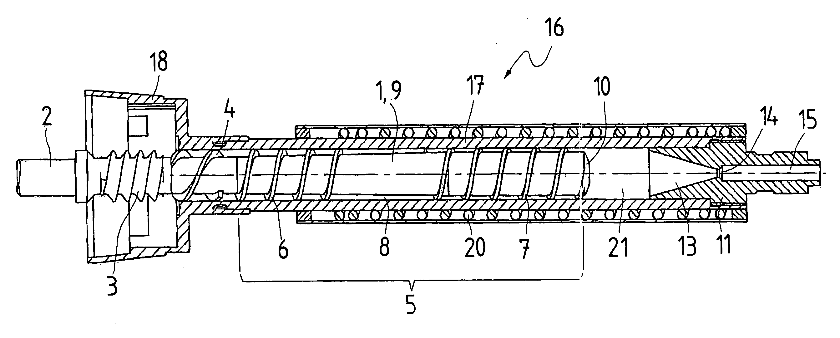
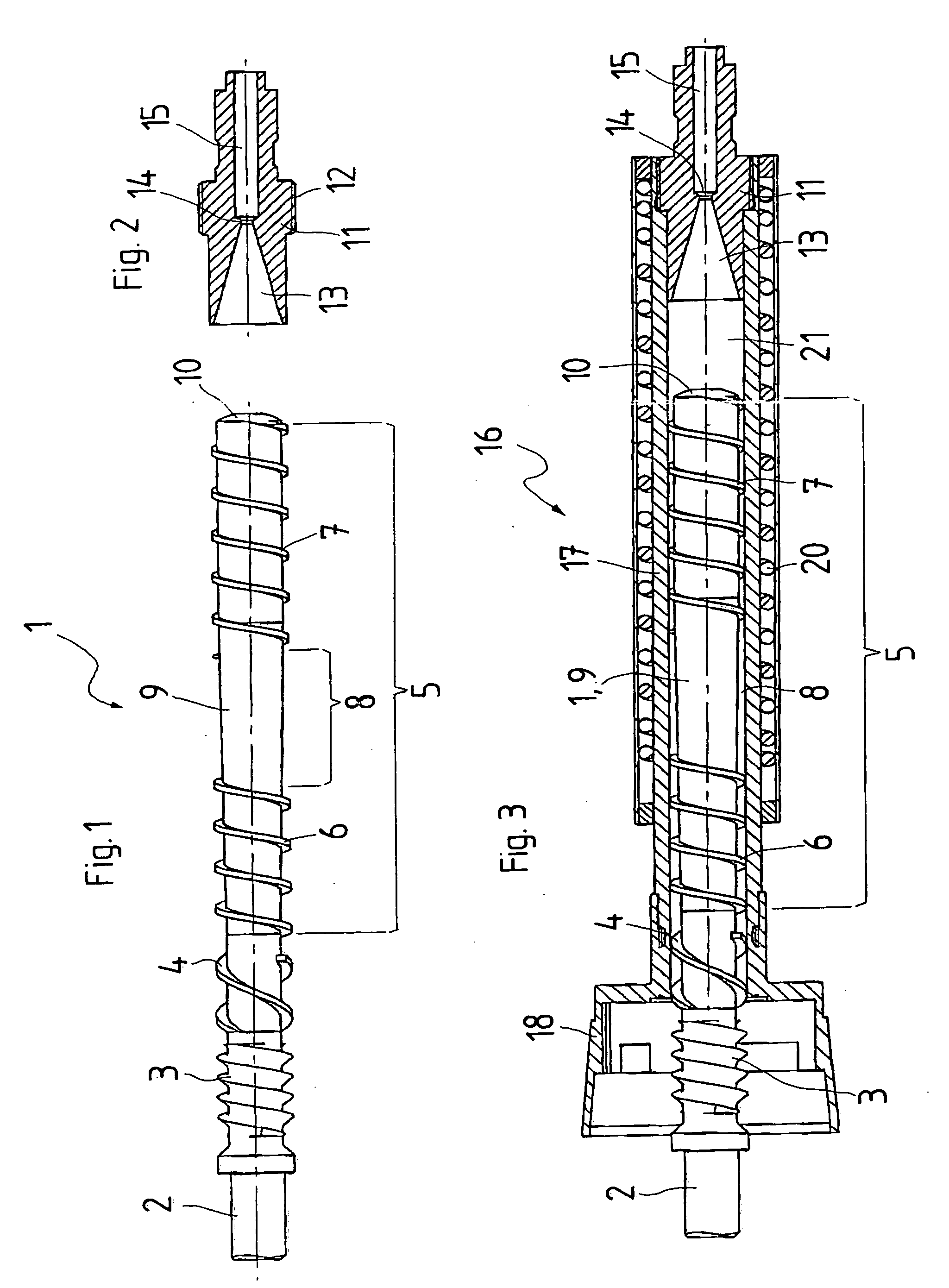
[0004] The invention solves this problem with the characteristics of claim 1. The extruder screw of the extruder proposed by the invention has two axially spaced screw threads. That means that the screw thread of the extruder screw is not continuous but that the extruder screw has a thread-less axial area between its screw threads. The thread-less area forms a buffer zone that serves as a storage space for the not yet completely plasticized compound, on the one hand, and as a degassing zone, on the other hand. Gas, in particular air, included in the synthetic material that is to be extruded but not completely plasticized yet, is expelled against the feeding direction from the synthetic material by the increasing compression of the not yet fully plasticized synthetic material, and flows from the thread-less buffer zone against the feeding direction of the extruder back to an inlet or feed opening for the synthetic material. In the area of the screw thread of the extruder screw that comes first in relation to the feeding direction, the synthetic material to be extruded is still present in the form of pieces that may already be partially plasticized and fused together. In the area of the screw thread of the extruder screw that comes first in relation to the feeding direction, the density of the synthetic material is still low enough to leave sufficient space between the synthetic material pieces for the air displaced in the buffer zone to escape against the feeding direction, i.e. towards the fill or feed end of the extruder. The buffer zone without a screw thread between the two screw threads of the extruder screw of the extruder proposed by the invention has the effect of degassing the synthetic material to be extruded against the feeding direction of the extruder. Gas inclusions in the plasticized synthetic material exiting from the extruder are avoided completely, or at least to a very large extent.
[0006] Another advantage of the extruder screw proposed by the invention is that it allows the use of a simple extruder insert, also known as an extruder nozzle. With the extruder screw proposed by the invention, it is not necessary to use a special extruder insert with multiple deflection of the plasticized synthetic material, possibly even in radial direction, or to separate the plasticized synthetic material in the extruder into several strands by means of a perforated disk, etc. Such special extruder inserts are used in familiar extruders for homogenization, mixing, and pressurizing. Such special extruder inserts are chicanes for the plasticized synthetic material; they have dead zones, i.e. zones with low or zero feeding velocity of the plasticized synthetic material where the synthetic material gets caught for long periods and decomposes. Particles of decomposed synthetic material will then lead to faults in the extruded synthetic compound.
[0008] One design variant of the invention provides for a smoothing space in the extruder housing in feeding direction behind the extruder screw and in front of an extruder insert. Preferably, this smoothing space is free of inserts / obstructions. In this smoothing space, an expansion, mixing, and further homogenization of the synthetic material plasticized by the extruder screw takes place. In addition, the smoothing space has the function of a second storage that makes the exit of the plasticized compound from the extruder more uniform and further reduces the pulsation of the exiting synthetic material.
[0009] One design variant of the invention provides for a simple extruder insert that tapers like a funnel in the feeding direction. Such an extruder insert that is easy to manufacture and avoids a complex flow path of the plasticized synthetic material, its separation into several strands, expansion in a gap, or similar features is made possible by the extruder screw proposed by the invention. The extruder insert offers favorable flow, minimizes shear forces, and reduces self-heating of the extruded synthetic material to a minimum. As an additional advantage, it has no dead zones where plasticied compound might collect and remain for long periods, and decompose.
[0010] A development of this design variant provides for the extruder insert to have no dead zone in the area of its funnel-shaped taper. Thus, the extruder insert has no inserts, additions inside or ahead of it, and no undercuts etc. that might create, in feeding direction, a dead flow zone or a zone of turbulence behind them, i.e. a zone with reduced flow velocity and / or a long dwell time of the plasticized synthetic material. Specifically, a decrease to a low feed velocity dropping towards zero, and / or a long dwell time of the plasticized synthetic material in the funnel-shaped taper of the extruder insert is to be avoided because this poses the danger of a decomposition of the synthetic material.

Problems solved by technology

Particles of decomposed synthetic material will then lead to faults in the extruded synthetic compound.

Method used


Image

  • Extruder, specifically an extrusion welding device
  • Extruder, specifically an extrusion welding device

Examples


Embodiment Construction

[0017] Shown in the figure from left to right, i.e. in the feeding direction, the extruder screw 1 proposed by the invention and shown in FIG. 1 has a drive shaft 2, a feed screw 3, a chopping screw 4, and the actual extruder screw 5. The drive shaft 2 serves to rotate the extruder screw 1, may be cylindrical or conical, and is preferably designed with a profiled cross-section for a positive transfer of the rotary motion. For this purpose, various positive-lock shaft clutches are known that are not described in detail here.

[0018] The feed screw 3 has a grooved screw thread with a sawtooth profile. Its purpose is to pull the synthetic material to be extruded. supplied in the shape of a wire (plastic welding wire, also known as rope or strand), into the extruder.

[0019] The chopping screw 4 is double-threaded, extending over approximately one thread, i.e. it is relatively short axially, and has a steep pitch. At its front ends in feeding direction, the chopping screw 4 has cutters, c...


PUM

PropertyMeasurementUnit
Diameteraaaaaaaaaa
Areaaaaaaaaaaa

Abstract

The invention concerns an extruder, specifically a hand-held extrusion welding device. For the purpose of degassing a synthetic material to be extruded that is already partially plasticized in the extruder, the invention proposes a thread-less area between two screw threads of an extruder screw. The compression of the synthetic material to be extruded expels gas from the synthetic material, the expelled gas flows against the feeding direction, and exits from the extruder at a feed opening. The extruder proposed by the invention offers the advantage of a complete, or at least an almost complete, degassing of the plasticized synthetic material.

Description

TECHNICAL FIELD [0001] The invention concerns an extruder, specifically an extrusion welding device, with an extruder housing and a power-driven extruder screw rotating in the extruder housing. BACKGROUND OF THE INVENTION [0002] Such extruders, in particular in the shape of hand-held devices, are commonly used for welding thermoplastic synthetic materials. The extruder housing is usually of tubular shape with a circular cross-section. Essentially, the powered rotating extruder screw has the functions of feeding and compressing the synthetic material to be extruded, of homogenizing (mixing, kneading) and thereby plasticizing it, and of extruding it from a nozzle. Also, solid and liquid additives such as dyes and fillers, stabilizers and lubricants are mixed homogeneously with the synthetic material to be extruded by the powered rotation of the extruder screw. It is a familiar feature of extruder welding devices that the synthetic material to be extruded is supplied as a granulate or ...

Claims


Application Information

Patent Timeline
IPC IPC(8): B29B7/42B29C48/64B29C65/12
CPCB29C47/0002B29C47/0009B29C47/62B29C65/12B29C66/836B29K2101/12B29C47/6018B29C47/6093B29C47/6025B29C66/861B29C48/02B29C48/03B29C48/53B29C48/535B29C48/63B29C48/64
Inventor PETERS, CHRISTIANNIEDERBERGER, ADOLPMICELI, GUISEPPE DI
Owner LEISTER PROCESS TECH
Learn More