
Method and device for battery charger and diagnosis with detectable battery energy barrier

a technology of detection and battery energy barrier, which is applied in the direction of home appliance efficiency improvement, transportation and packaging, sustainable buildings, etc., can solve the problems of unblanced internal resistance between cells, safety problems, and battery capacity decrease, so as to achieve the effect of reducing current and voltage noise during charge, reducing the charge efficiency of lead-acid battery packs, and achieving full charge ratio

Inactive Publication Date: 2006-07-06
JASON AUTO TECH
View PDF2 Cites 101 Cited by
  • Summary
  • Abstract
  • Description
  • Claims
  • Application Information

AI Technical Summary

Benefits of technology

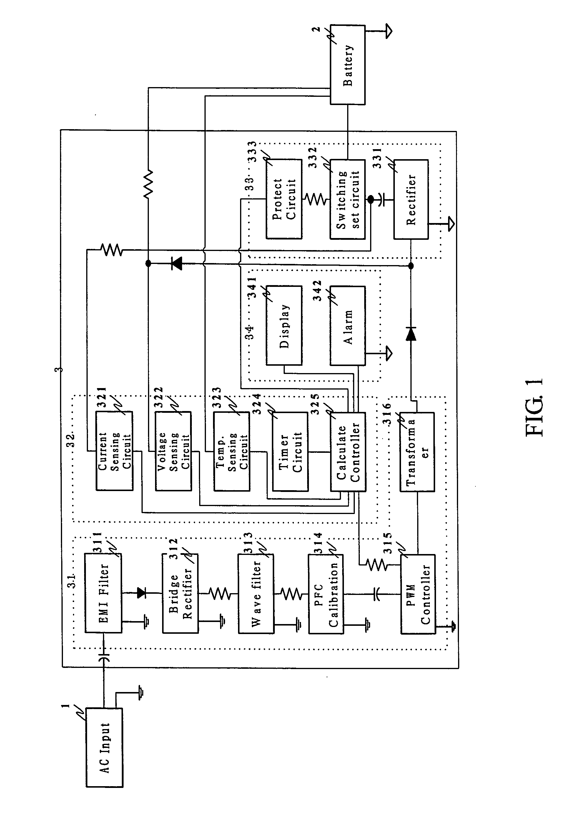
"The invention provides a self-adaptive charge and diagnosis method and device with detectable BEB function. It uses the measurement and characteristics of the BEB during charging to improve previous charging methods. The device includes a bridge rectifying circuit, secondary control circuit, and a calculator control unit to determine the battery's charge status. The method allows for efficient charging, reduces noise, and promotes a full charge. Additionally, the device can actively monitor the battery's status and use different charging methods based on its status to enhance its life cycle. The invention also provides an alternative method to indicate the energy difference between the battery and the charging side, and can alarm and display abnormal battery status."

Problems solved by technology

During the repeatedly charging and discharging process, if the battery is kept in the over-charge status with high current or high temperature, the materials within the battery would be passivation, consequently decreasing battery capacity, or even causing safety problem.
However, the internal resistance of each cell is different in normal, exhaust chemical material passivation or electric leakage which then causes internal resistances between cells unblance.
Therefore, the charge method only with the use the constant high current or constant pulse frequency and amplitude is hard to fit each battery cell, and also there occur the latent variables of charge efficiency and safety.
Their relationships are very complicated and involve with many variables, so finding the most suitable charge curve is limited by the applicability to all different situations, as in Republic of China Patent 583408.
This kind of rapid charge would accelerate the decline of the activity of the plate surface of the lead-acid battery, even result in the excessive deposit of lead sulfate, and finally shorten the lifetime of lead-acid batteries.
Because rechargeable battery are widely employed in various electronic products and mobile vehicles or ships, the problems concerning the correct and safe full-charge, and the charge methods causing no decrease in battery lifetime are always the main task for chargers.
In practicle application, it remains a problem that how to select the voltage set-point or current set-point, or the mix of them to realize full and safe charge, and at the same time to keep the battery lifetime.
If charge the battery with energy excessively higher than BEB, then there might occur the violent reverse chemical reaction that would overly activate the battery, and perhaps cause over-high temperature in the battery, and might cause the unbalanced over-activation of a single cell, and once in a while lead to battery passivation or even explosion.
The result of a simple voltage measurement or current measurement cannot directly reveal the BEB between the battery pack and the charge energy.
It is impossible for the multi-stage charger to be widely applicable to different situations, such as different state of charge battery or whether the battery is normal.

Method used


Image

  • Method and device for battery charger and diagnosis with detectable battery energy barrier
  • Method and device for battery charger and diagnosis with detectable battery energy barrier
  • Method and device for battery charger and diagnosis with detectable battery energy barrier

Examples


Embodiment Construction

[0079] Corresponding a vehicle battery system reference characters indicate corresponding method and parts throughout the several views. The exemplifications set out herein illustrate a preferred embodiment of the invention, in one form thereof, and such exemplifications are not to be construed as limiting the scope of the invention in any manner.

[0080] Lead-acid battery pack: 24 VDC-24 AH

[0081] AC input terminal: 230 VAC±10%, 50˜60 Hz

[0082] Circuit working voltage Vcc: 16 VDC

[0083] DC voltage: 400 VDC

[0084] Charger power: 24V-2 A

(1) Measurement Method for the BEB of a Preferred Embodiment of this Invention

[0085] There existing an energy gap between battery energy and charge energy, as while in charging, the input charge energy must overcomes the battery energy. As shown in the following equation:

ΔE(t)=Ec(t)−Ecell(t)

where Ec(t) refers to the energy supplied by the charger appliance at time t, Ecell(t) is the battery energy. ΔE(t)≧0 signifies that the charger output energy...


PUM


Abstract

Methods and device for battery charging and diagnosis provide a measuring batter energy state in which charging strategy alternate with the minimize balance between battery energy state and charging energy in which the balance is existed in battery energy barrier. Variance battery energy barrier derives adaptive charging cycle and charging protection in to approach the requirements of safety, full charge and high performance for lead-acid battery. The charging cycle derives protection mode to adapt the initial battery energy barrier state, and derives diagnosis mode to adapt electrolyte activities diffusion state, and derives the charging mode in optimum strategy to adapt polarization, storage and saturation cycle by using measure battery energy barrier, and derives the alert indication mode to result the charging cycles and diagnosis, in which the output charging energy is derived as continuous and minimum energy in inhibit of reduce efficiency due to the violent agitation and the fluctuation phenomenon in appearance in charging cycle. This invention comprise Primary power supply unit, measurement and control unit, secondary side control unit and alert / indication unit to feature the functions with stable, safety, full charging, high efficiency, diagnostic and longevity charger.

Description

BACKGROUND OF THE INVENTION [0001] The present invention relates to a method and device for battery charger and diagnosis with detectable battery energy barrier, which is a method concerning the measurement of battery charge status, and the derivation of the charge method suitable for the battery status, and the diagnosis of whether the battery is normal. In the actual circuit implementation of this invention, the safety, efficiency and full-charge of lead-acid batteries can be achieved. [0002] For the techniques of charging rechargeable batteries, the characteristics of full-charge and safety are required. For the charge of lead-acid batteries, it is even further required not to decline the battery lifetime. These have been mentioned in the report proposed by T. Ikeya etc. in J. of Power Sources (Vol. 69, No. 1-2) in November, 1997, and the one by H. Oman in IEEE Aerospace & Electronics Systems Magazine (Vol. 14, No. 9) in 1999. During the repeatedly charging and discharging proces...

Claims


Application Information

Patent Timeline
Patent Type & Authority Applications(United States)
IPC IPC(8): H02J7/00
CPCH02J7/0047H02J7/0072Y02B40/90H02J7/00714H02J7/0049H02J7/007182H02J7/007194Y02B40/00
Inventor WANG, JEEN-SHUH
Owner JASON AUTO TECH
Learn More