
Sensing mechanical transitions from current of motor driving hydraulic pump or other mechanism

a technology of mechanical transition and current sensor, which is applied in the direction of motor/generator/converter stopper, electric controller, dynamo-electric converter control, etc., can solve the problems of potential safety problems, increase the cost and circuit complexity and increase the cost of the person on the platform

Active Publication Date: 2006-07-06
INPOWER LLC
View PDF9 Cites 12 Cited by
  • Summary
  • Abstract
  • Description
  • Claims
  • Application Information

AI Technical Summary

Benefits of technology

[0036]FIG. 6 is a graph of hydraulic pressure for a lift system as the platform is raised from ground level through its fully stowed position.
[0037]FIG. 7 is a graph of hydraulic motor current for a lift system as the platform is raised from ground level through its fully stowed position.

Problems solved by technology

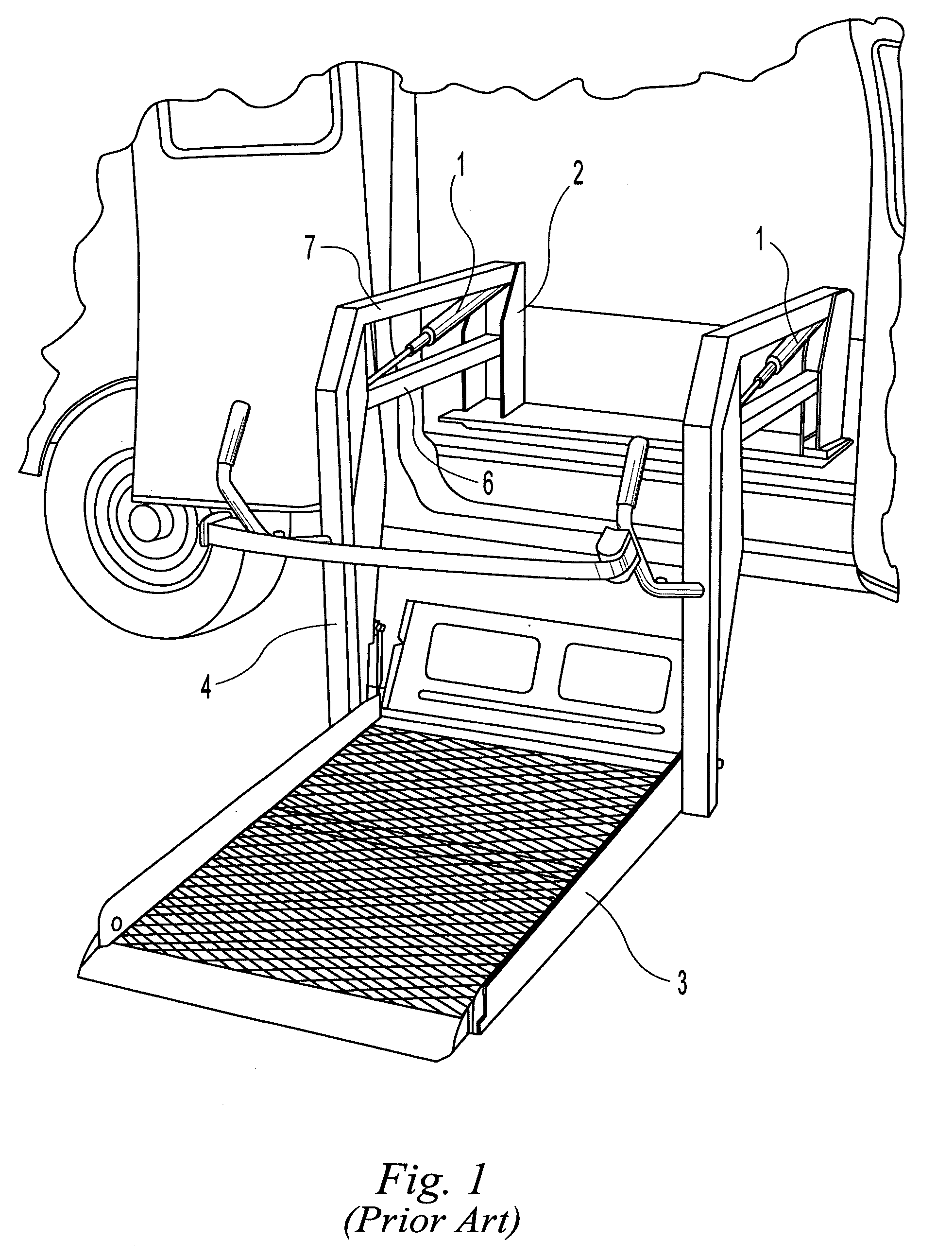
The electric motor is not directly switched on and off by a mechanical, hand-held switch because the motor currents are too large and would require an excessively large electrical cable in the user's hand to control the lift.
Examining the schematic in FIG. 4 reveals a potential safety problem.
Serious injuries could result to a person on the platform.
Redundant position-sensing control switches can increase reliability but they do so at the expense of increased cost and circuit complexity.
Furthermore, what happens if the two redundant switches operate from the same cam and that cam fails?
A light beam sensing system adds considerable expense and circuit complexity and provide additional structure that can be damaged during use and therefore disable the system and require repair.

Method used


Image

  • Sensing mechanical transitions from current of motor driving hydraulic pump or other mechanism
  • Sensing mechanical transitions from current of motor driving hydraulic pump or other mechanism
  • Sensing mechanical transitions from current of motor driving hydraulic pump or other mechanism

Examples


Embodiment Construction

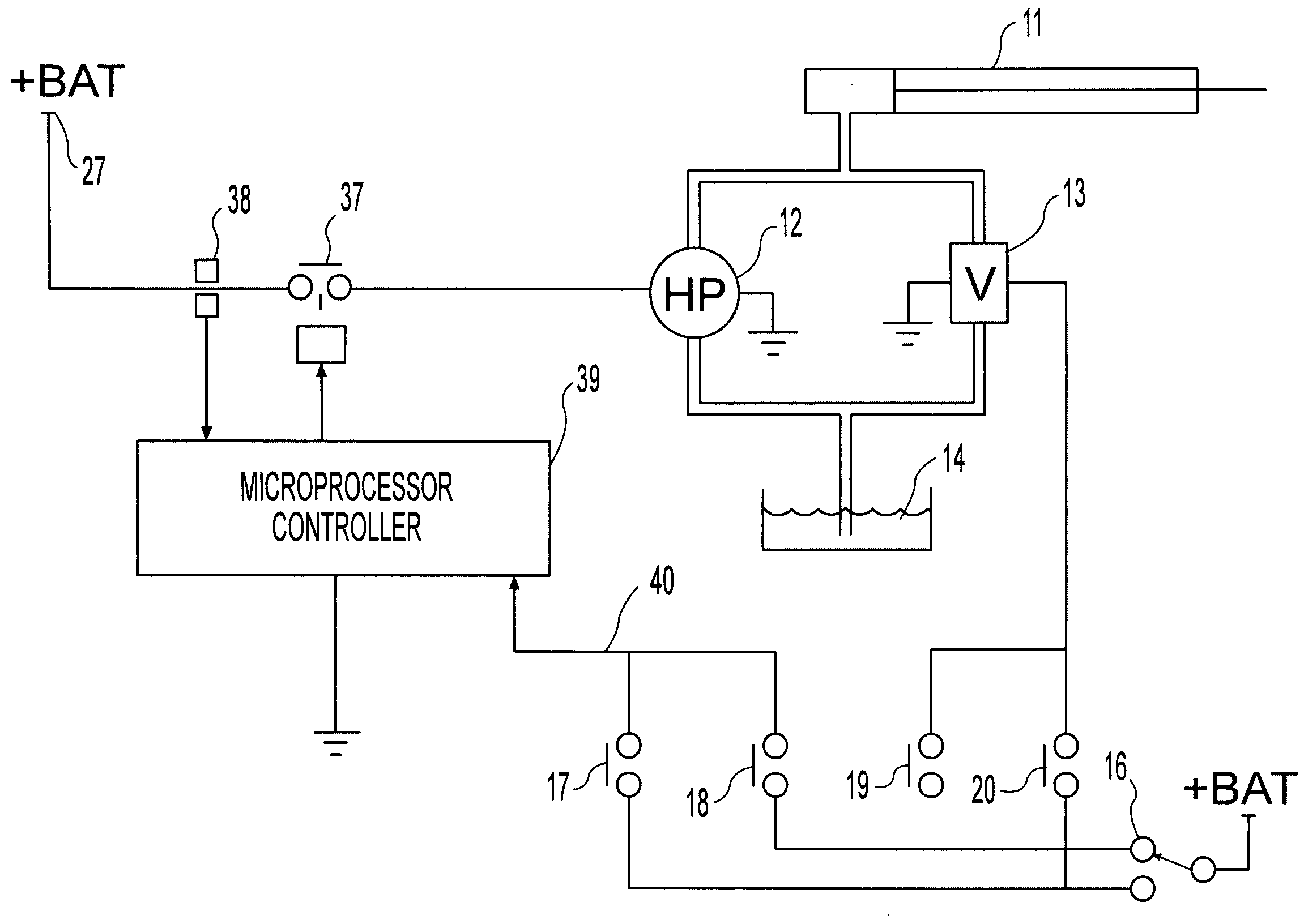
[0040] The present invention is illustrated with respect to a wheelchair lift system that includes an electric motor driven hydraulic pump actuating a hydraulic cylinder to perform platform lifting and stowing functions. The invention monitors the electric motor load current to determine if the lifting platform is erroneously transitioning from its lifting cycle into its stowing cycle. Detection of the erroneous transition is used to provide a back up safety shut down of the hydraulic motor in the event that a primary position-sensing device, such as a limit switch, fails to sense the arrival of the platform at a particular position. However, the invention could be the primary position sensing device and also is adaptable and applicable to other systems having an electric motor powering a mechanical apparatus.

[0041] A Circuit Embodying The Invention

[0042] The components of the preferred embodiment of the invention are shown in FIG. 5. As is apparent from this schematic diagram, th...


PUM


Abstract

A circuit and method for detecting an operating transition of a mechanical apparatus driven by a hydraulic prime mover comprising a hydraulic pump driven by an electric motor, the operating transition causing a change in the force applied by the mechanical apparatus on the prime mover. A motor current sensing circuit is connected in a motor power supply circuit to provide a motor current signal representing motor current. A bandpass filter receives the motor current signal and provides a filtered motor current signal consisting essentially of motor current signal components in the frequency range from a lower frequency boundary greater than zero Hz to an upper frequency boundary below substantially all the motor noise frequencies. A comparison circuit compares the filtered motor current signal to a first selected threshold level and outputs a signal representing the occurrence of the operating transition when the filtered motor current signal exceeds the selected threshold level. The circuit is preferably implemented with a digital controller programmed to perform these operations.

Description

(e) BACKGROUND OF THE INVENTION [0001] 1. Field Of The Invention [0002] This invention relates generally to systems having an electric motor driving a mechanical apparatus and more particularly relates to the detection of mechanical loading transitions of the mechanical apparatus by monitoring motor current and is particularly useful as a backup system to conventional limit switches of other devices commonly used to detect the position of a component of the mechanical apparatus. [0003] 2. Description Of The Related Art [0004] There are many types of machines that transport people or move mechanical apparatus in the vicinity of people or otherwise require reliable control so they do not malfunction and cause personal injury or property damage. One of the most common electrical loads associated with such machines is an electric motor that is or drives a prime mover to move the mechanical apparatus. Such machines should not only operate when they are signaled or otherwise commanded to ...

Claims


Application Information

Patent Timeline
Patent Type & Authority Applications(United States)
IPC IPC(8): H02P1/24H02P1/42
CPCA61G3/061
Inventor SULLIVAN, JAMES D.
Owner INPOWER LLC
Learn More