
Scan conversion device and electronic camera

Inactive Publication Date: 2006-06-22
NIKON CORP
View PDF3 Cites 8 Cited by
  • Summary
  • Abstract
  • Description
  • Claims
  • Application Information

AI Technical Summary

Benefits of technology

[0010] It is therefore an object of the present invention to provide a novel technique for converting a scan pattern of an input image.
[0011] It is another object of the present invention to add processing of a pixel signal pack (described later) to the scan pattern conversion processing, thereby improving efficiency and speed of the conversion processing.
[0012] It is still another object of the present invention to scan and output pixel signals using a converted scan pattern through a plurality of output channels, achieving an increase in a processing rate in later signal processing.
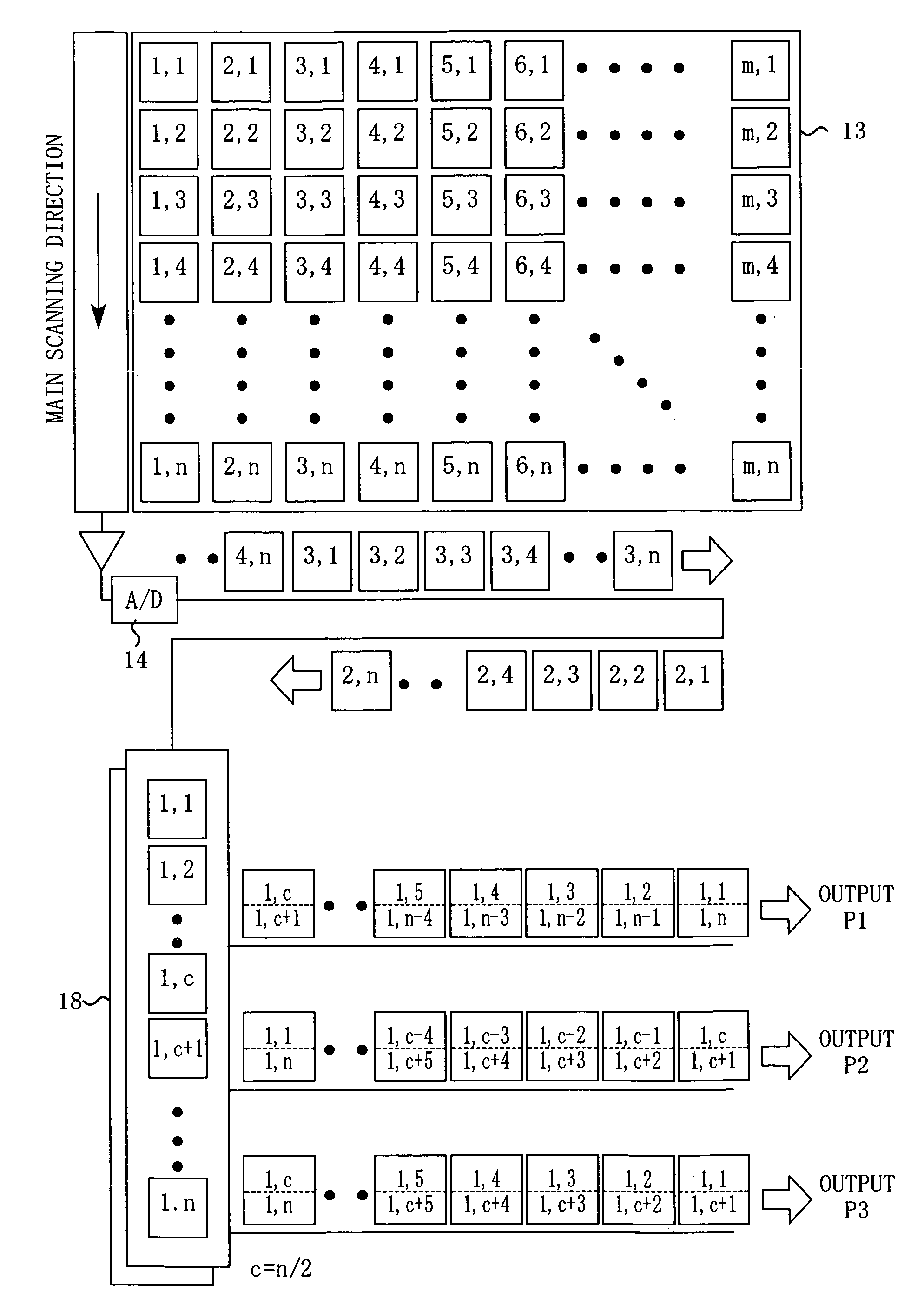
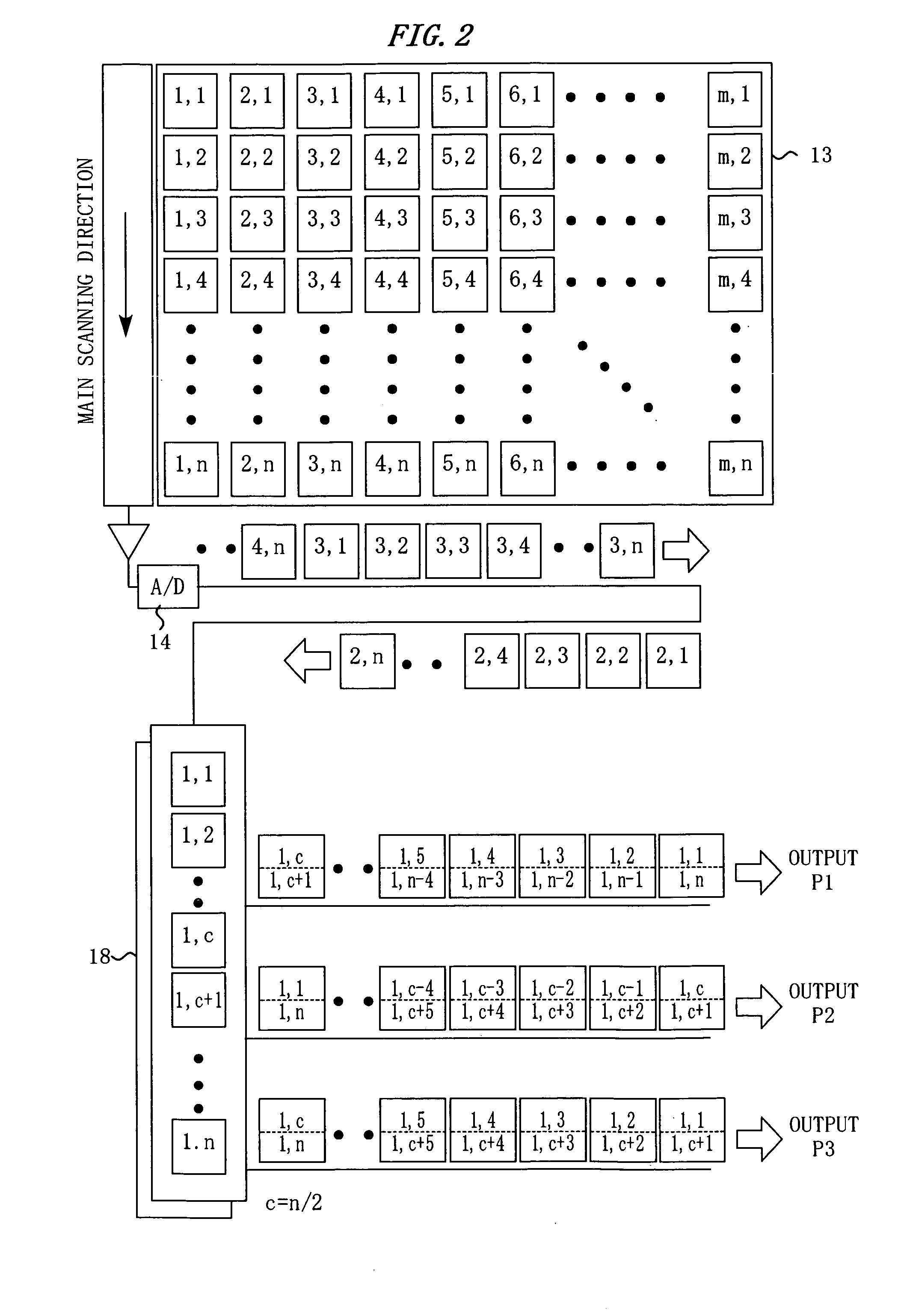
[0018] According to this configuration, it is possible to change a scan pattern of the input image into a scan pattern in which every N output lines in the second main scanning direction are output.
[0024] According to this configuration, it is possible to change the scan pattern of the input image into a scan pattern in which N divided regions in the screen are scanned for output in parallel (i.e., N-blade scan which moves similarly to a N-blade razor skimming the screen).

Problems solved by technology

Recent increase of the number of pixels of an imaging device has caused much increase of time required for reading out data from the pixels thereof.
However, there is a problem in using a plurality of output channels that it is required to provide a plurality of paths for transferring the pixel signals in the imaging device, which limits the design of the imaging device in terms of device layout, signal interference, and the like.
As described above, the restriction to the scan pattern causes various troubles in later signal processing.
For example, when adjacent pixel signals on the screen are output at different timings, it is not possible to align, in a pipeline way, pixel signals of the minimum processing unit for signal processing.
In addition, if a pixel signal required first in signal processing is output later, the signal processing will be delayed.

Method used


Image

  • Scan conversion device and electronic camera
  • Scan conversion device and electronic camera
  • Scan conversion device and electronic camera

Examples


embodiment 1

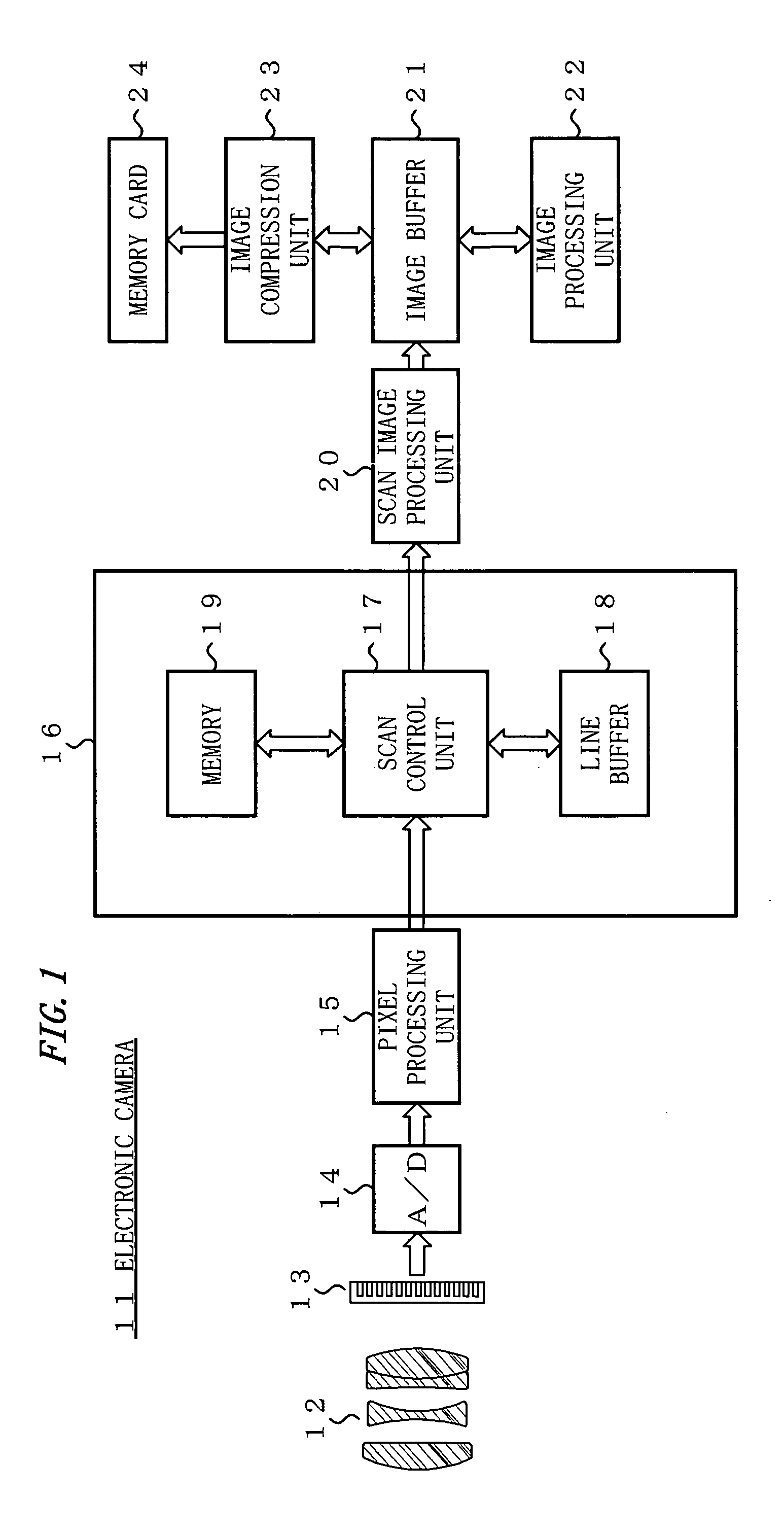
[0040]FIG. 1 shows the configuration of an electronic camera 11.

[0041] Referring to FIG. 1, a lens 12 is mounted on the electronic camera 11. A light-receiving surface of an imaging device 13 is arranged in an image space of the lens 12.

[0042] Pixel signals output from the imaging device 13 are converted into digital signals by an A / D converter 14 and are then input to a pixel processing unit 15 sequentially. The pixel processing unit 15 performs one or more processings feasible for each one of the pixel signals independently (e.g., correction for a defective pixel) in a pipeline manner. The thus processed pixel signals are input to a scan conversion device 16.

[0043] The scan conversion device 16 includes a scan control unit 17, a line buffer 18, and a memory 19. The line buffer 18 temporarily stores pixel signals corresponding to a read-out line in a main scanning direction of the imaging device 13. The memory 19 is a buffer which can be read from and written to at least on a pi...

embodiment 2

[0080] Next, the imaging device 13 in the electronic camera 111 scans the pixel signals and outputs them on a plurality of channels.

[0081]FIG. 6 shows a pixel arrangement in an imaging device 13. The imaging device 13 generates pixel signals of n pixels in the vertical direction×m pixels in the horizontal direction. The pixel signal is a color signal containing information on one of colors, Gr, Gb, R, and B. These colors are arranged in a bayer pattern.

[0082]FIG. 7 shows four scan outputs chA, chB, chC, and chD of the imaging device 13.

[0083] As shown in FIG. 7, the imaging device 13 divides pixel signals of the pixels arranged as shown in FIG. 6 into a first field formed of R lines and Gr lines and a second field formed of Gb lines and B lines and reads the pixel signals out by sequentially reading the first field and the second field, i.e., performing reading twice.

[0084] R components of the first field are divided into two groups that are respectively read out on two scan out...


PUM


Abstract

A scan conversion device includes a first buffer unit, a pixel packing unit, a second buffer unit, and a scan output unit. The first buffer unit stores therein pixel signals of the input image on every line in a main scanning direction thereof. The pixel packing unit groups N (N≧2) pixel signals on each line into pixel signal packs according to a predetermined pixel combination rule, and outputs them sequentially. The second buffer unit stores therein the pixel signal packs and aligns them in a second main scanning direction different from the main scanning direction. The scan output unit sequentially outputs the pixel signal packs aligned in the second main scanning direction. According to this configuration, a scan pattern of the input image is changed into a scan pattern of outputting every N output lines in the second main scanning direction.

Description

CROSS REFERENCE TO RELATED APPLICATION [0001] This application is based upon and claims the benefit of priority from Japanese Patent Application No. 2004-366037, filed on Dec. 17, 2004, the entire contents of which are incorporated herein by reference. BACKGROUND OF THE INVENTION [0002] 1. Field of the Invention [0003] The present invention relates to a scan conversion device for converting a scan pattern of an input image. The present invention also relates to an electronic camera that includes the scan conversion device. [0004] 2. Description of the Related Art [0005] Recent increase of the number of pixels of an imaging device has caused much increase of time required for reading out data from the pixels thereof. Providing a plurality of number of output channels for the imaging device to heighten a rate of pixel readout is a way to solve this problem. [0006] For example, there is a known technique in which pixel signals from the imaging device are divided in a unit of regions of...

Claims


Application Information

Patent Timeline
IPC IPC(8): H04N1/04G06T1/60H04N5/232H04N5/335H04N5/341H04N5/345H04N7/01H04N101/00
CPCH04N1/0402H04N1/0417H04N2101/00H04N2201/0084
Inventor MORISHITA, AKIHIKO
Owner NIKON CORP
Learn More