
Plasma processing method

Inactive Publication Date: 2005-08-30
SHARP KK
View PDF21 Cites 3 Cited by
  • Summary
  • Abstract
  • Description
  • Claims
  • Application Information

AI Technical Summary

Benefits of technology

[0028]A second object of the present invention is to provide a plasma processing on a semiconductor device which can achieve a decrease in cost while increasing a processing rate in a plasma processing. The present invention has been thought for solving the above problems.
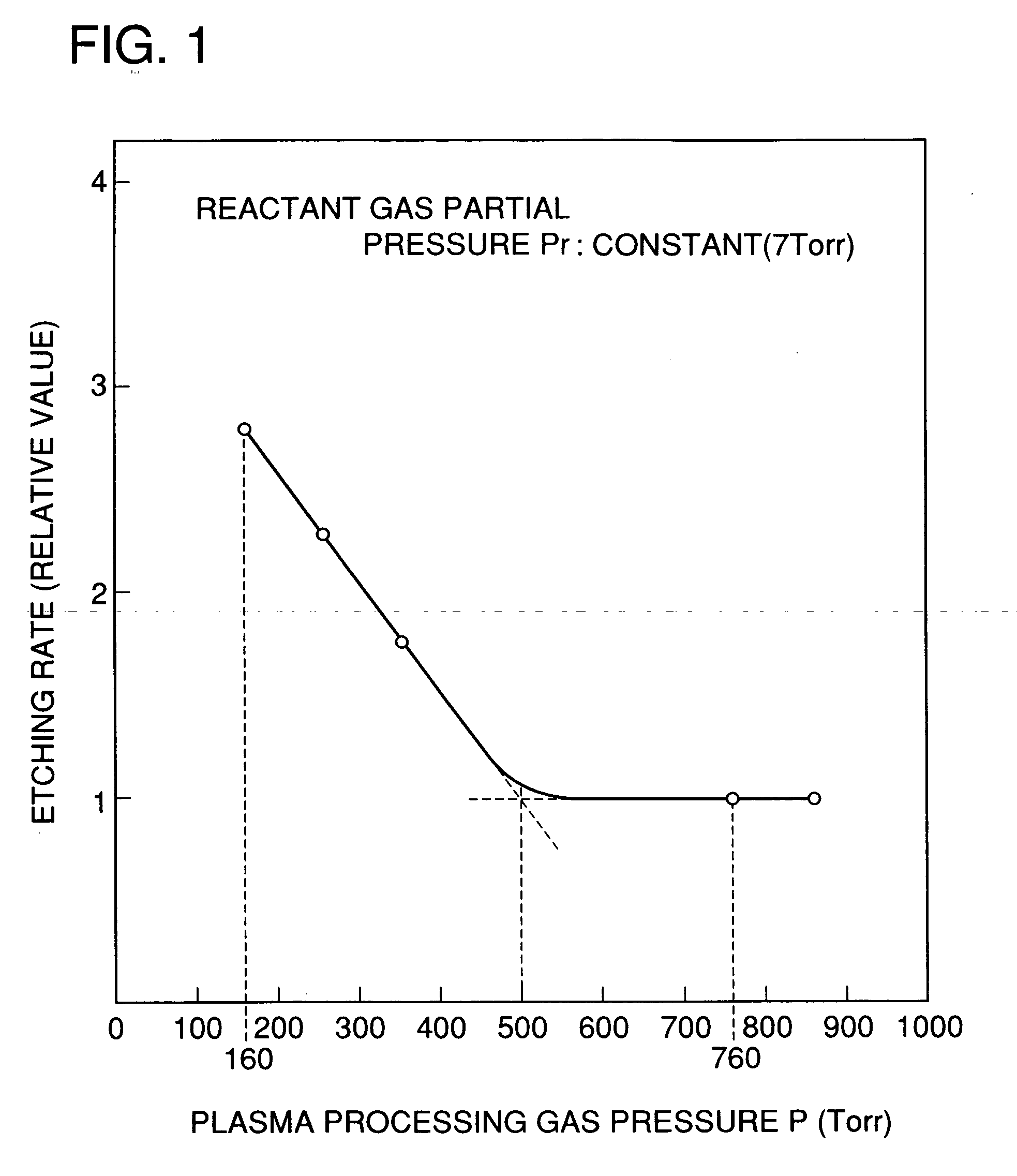
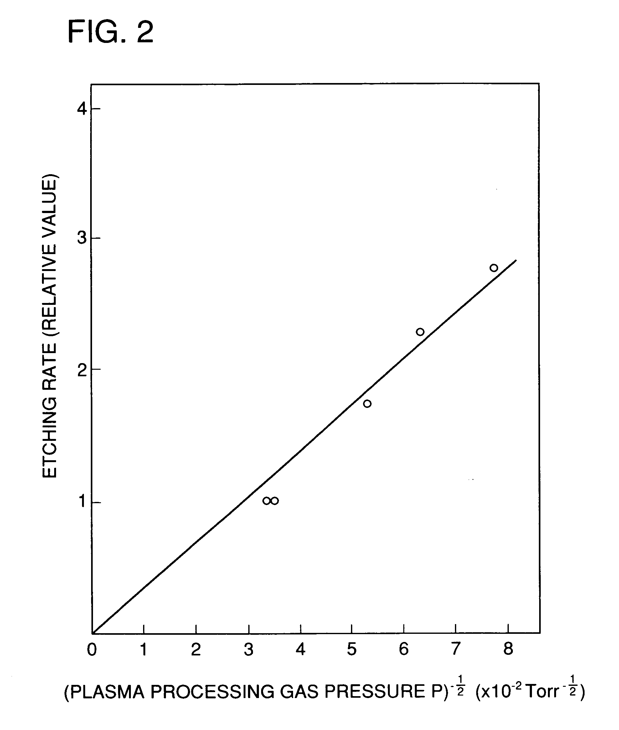
[0032]That is, the present invention specifies a pressure range of the plasma processing gas used in association with a cycle of high-frequency power to thereby provide an increase in a processing rate and reduction in cost under the condition that the high-frequency power is constant and a reactant gas is constant in partial pressure.

Problems solved by technology

However, when the reactant gas is raised in pressure, it becomes difficult to generate plasma stably.
Also, because pressure of the plasma processing gas is near the atmospheric pressure, it is unnecessary to evacuate an interior of the reaction vessel for vacuum.
In plasma processing in recent years, however, the demand for increasing a processing rate is very strict, as typified by the manufacturing process for amorphous Si solar cells.
However, the publications do not present any guideline for increasing the processing rate for a constant partial pressure of the reactant gas.
In particular, the He gas used in large amount is expensive, and so a ratio of cost required for the He gas becomes great taking account of cost per device in mass-production factories.
According to the above-described prior art, while cost required for installation can be decreased, cost required for consumable goods such as He gas increases, which leads to high cost, judging comprehensively.

Method used


Image

  • Plasma processing method
  • Plasma processing method
  • Plasma processing method

Examples


second embodiment

[0117]In the above first embodiment, the experimental results have been shown, in which SF6 gas first is used as a typical reactant gas. As described above, however, since it is thought that drift velocity of electrons dominantly contributes to the plasma processing rate, it can be estimated that the pressure range (the formula (A)) prescribed for a plasma processing gas is not dependent upon a type of a reactant gas, and is applicable to any reactant gas.

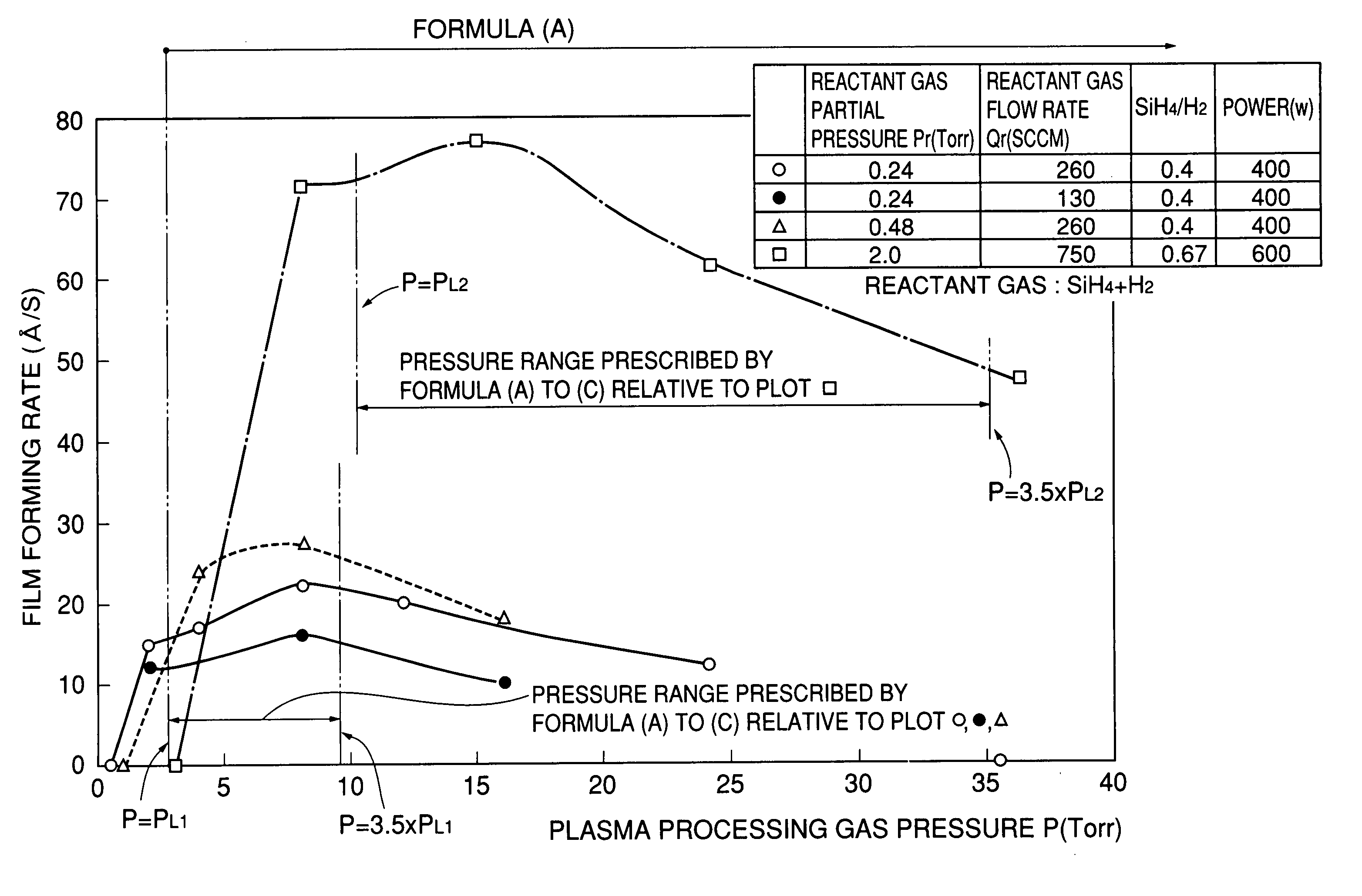
[0118]Hereupon, to confirm this, an experiment for forming a Si thin film on a glass substrate was carried out in the present embodiment, with the use of a mixture gas composed of SiH4 and H2 as a reactant gas.

[0119]In the present embodiment, an elaborate experiment was carried out at the plasma processing gas pressure P near the lower limit pressure PL1 prescribed in the formula (A), and it has been found that further addition of limitations indicated by the formulae (B), (C) to the condition prescribed in the formula (A) is effec...

modified example 1

[0140]In the above embodiment, the experimental results are demonstrated in the case where He is used as an inert gas. However, an inert gas in the present invention is not limitative. As an example, an experiment was carried out with the use of Ar as an inert gas. Experimental conditions are the same as shown by O plot in FIG. 8, and a plasma processing gas pressure P was 8 Torr. As a result, a film forming rate (deposition rate) was 25 Å / s, and there was not much difference as compared in the use of He. Also, an amorphous Si thin film which had the photo sensitivity of 5×10⁵ or more was obtained.

modified example 2

[0141]With respect to the above embodiments and the modified examples, an explanation has been given to the case where a plasma processing gas was a mixture gas of a reactant gas and an inert gas. However, the pressure range of a plasma processing gas prescribed by the formula (A) indicates one, in which drift velocity of electrons was increased by reduction in pressure. Accordingly, this point of view-holds true even if the plasma processing gas consists of only a reactant gas. In this case, however, increasing the drift velocity of electrons by decreasing the plasma processing gas P in pressure leads simultaneously to reduction in a reactant gas partial pressure Pr, and so it is necessary to contemplate trade-off of opposing effects. Also, to maintain plasma with only a reactant gas, it is necessary to load a large amount of high-frequency power.


PUM

PropertyMeasurementUnit
Dynamic viscosityaaaaaaaaaa
Pressureaaaaaaaaaa

Abstract

In a plasma processing method making use of a plasma processing gas of a reactant gas and an inert gas, it is aimed at enhancing an efficiency of use of high-frequency power and a reactant gas to increase a processing rate. The plasma processing method comprises supplying high frequency power to an electrode 2 opposed to a substrate 6 to thereby generate plasma between the electrode 2 and the substrate 6 on the basis of a plasma processing gas comprising a reactant gas and an inert gas to perform film formation, etching, surface treatment or the like on the substrate 6, pressure P(Torr) of the plasma processing gas being set to satisfy the following relationship 2×10⁻⁷(Torr / Hz)×f(Hz)≦P(Torr)≦500(Torr) where f(Hz) is a frequency of high frequency power.

Description

CROSS-REFERENCE TO RELATED APPLICATION[0001]This application is related to Japanese patent application No. Hei 11(1999)-096859 filed on Apr. 2, 1999, whose priority is claimed under 35 USC §119. the disclosure of which is incorporated herein by reference in its entirety.BACKGROUND OF THE INVENTION[0002]1. Field of the Invention[0003]The present invention relates to a plasma processing method for performing film formation (deposition), etching, surface treatment on a substrate and the like, and more particularly, to a plasma processing method for generating plasma based on a plasma processing gas to perform film formation (deposition), etching, surface treatment and the like for a thin film such as a semiconductor thin film, an insulating thin film and so on, and in particular specifying a pressure range of a plasma processing gas in association with a cycle of high-frequency power to thereby enable high speed processing.[0004]2. Description of the Related Art[0005]High rate processi...

Claims


Application Information

Patent Timeline
IPC IPC(8): B05D3/06H05H1/46B05D3/14B05D7/24C23C16/50
CPCC23C16/50H01J37/32082B05D1/62B05D3/141
Inventor TAKEUCHI, HIROAKIOKUDA, TOHRU
Owner SHARP KK
Learn More