Eureka AIR delivers breakthrough ideas for toughest innovation challenges, trusted by R&D personnel around the world.

Scanning head for a measuring device

a technology of measuring device and scanning head, which is applied in the direction of measuring device, electric/magnetic measuring arrangement, instruments, etc., can solve the problems of measurement errors, change in the feeler bending, and inability to corr

Active Publication Date: 2006-06-15
HEXAGON METROLOGY GMBH
View PDF7 Cites 59 Cited by
  • Summary
  • Abstract
  • Description
  • Claims
  • Application Information

AI Technical Summary

Benefits of technology

[0009] It is therefore an object of the invention to provide a scanning head of the measuring type for a coordinate measurement system having a damping device, which combines the flexibility of a regulator with the sturdiness of the eddy current principle.
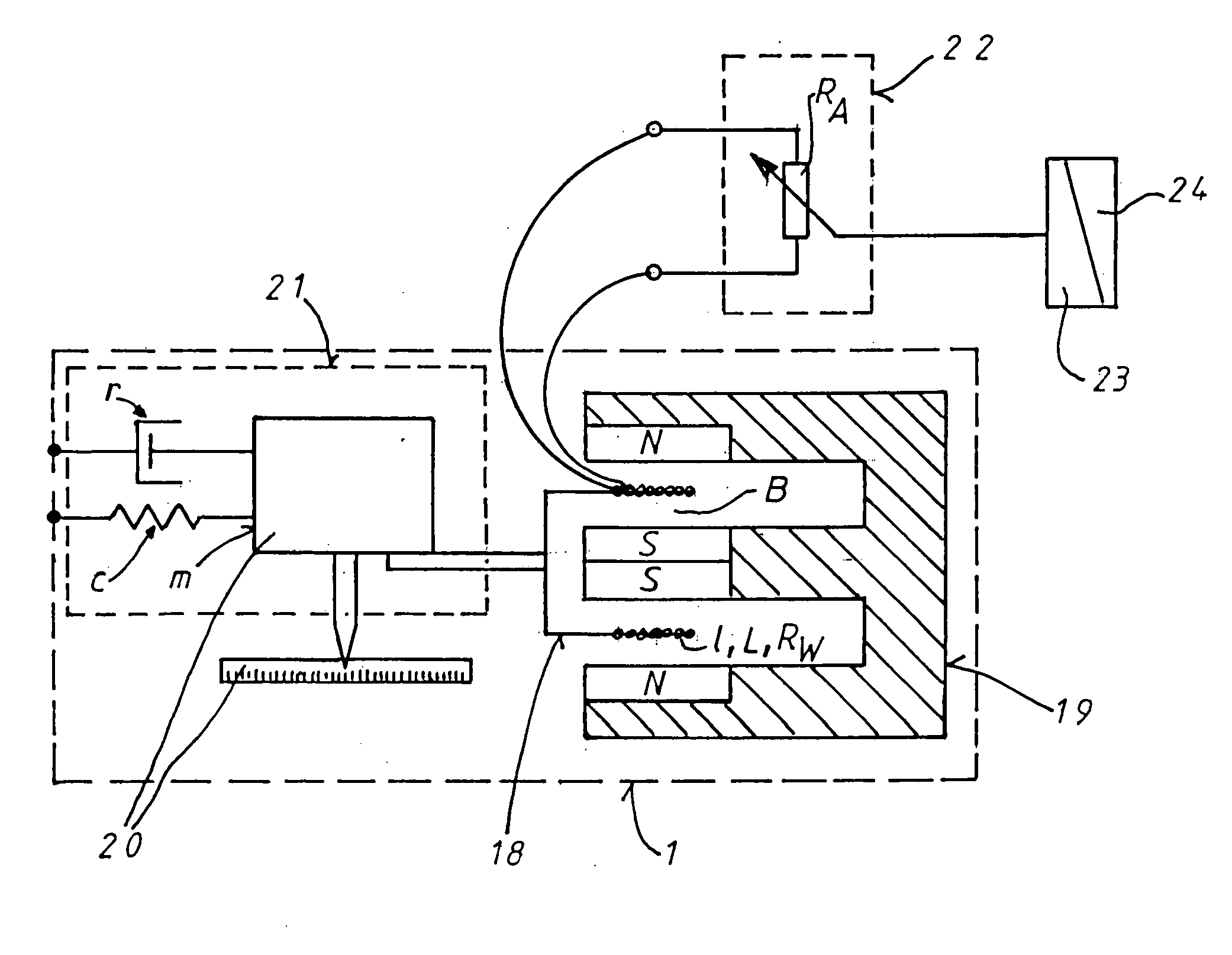
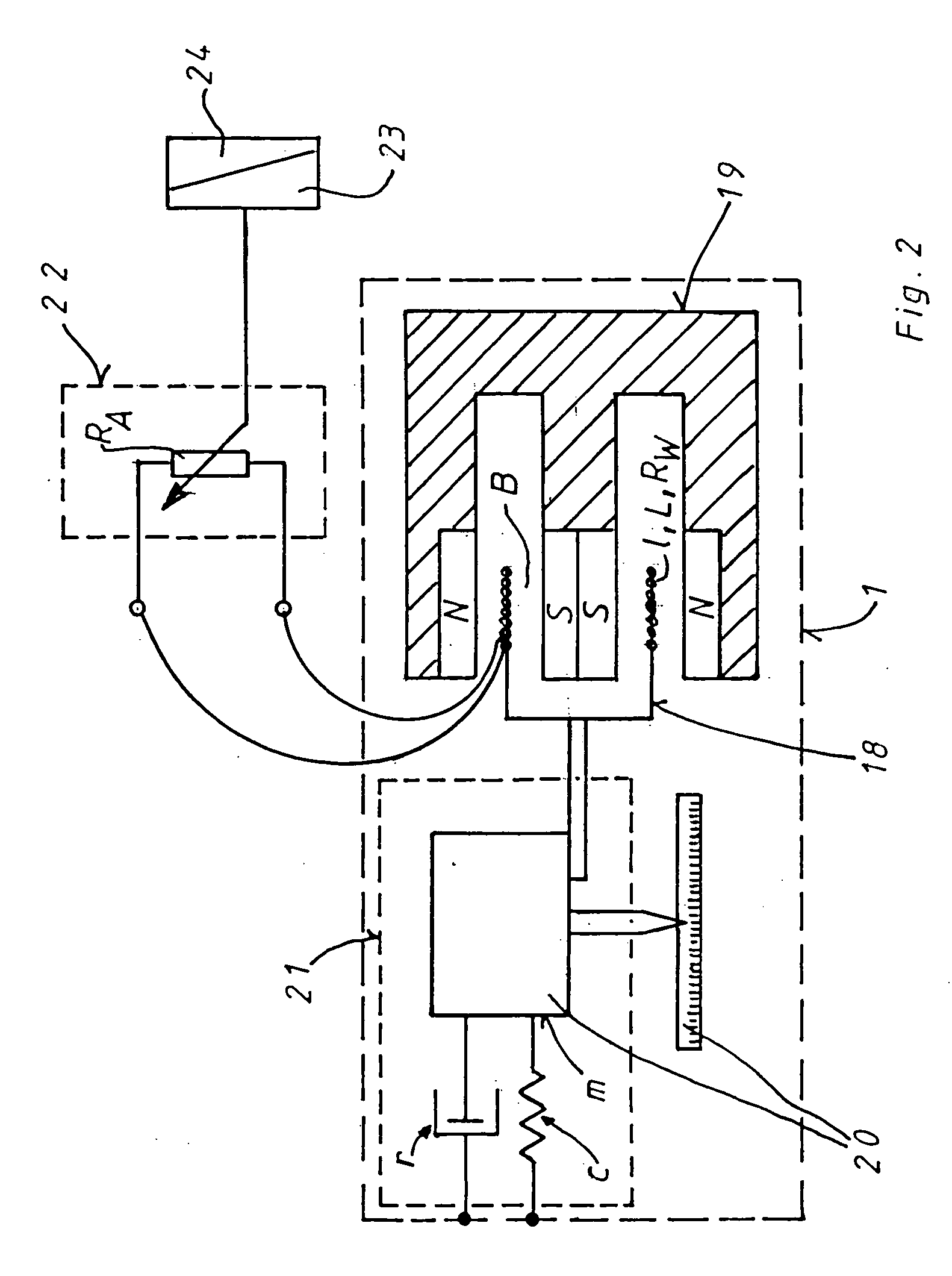
[0011] The damping device is preferably configured as a friction-free DC linear motor that is connected with at least one negative ohmic resistor. The scanning head according to the invention, having the damping device, is very flexible and, at the same time, robust.
[0013] If the winding resistance of a coil is almost compensated at room temperature, by connecting a negative ohmic resistance to the connector terminals, almost any desired current intensities are induced in the coil by means of the relative movement of the coil and the magnet, and this consequently allows the damping to increase suddenly. Because of this fact, the coils for use in the measurement head can be built very small, with the toleration of a higher winding resistance caused by thin winding wire, which is then compensated. The damping can be adjusted within broad ranges by means of the selection of the negative ohmic resistance value relative to the winding resistance. In contrast to the regulator, there is no status variable of the vibrating mechanical system here that should be regulated to a reference value, which variable would have to be monitored using a sensor. In contrast to the eddy current brake, the damping effect can be influenced, within broad limits, by manipulating the parameters of the negative resistance.

Problems solved by technology

In the case of tactile measurement of work pieces, using a coordinate measurement device, to which a scanning head as described above is attached, undesirable vibrations both of the support structures of the coordinate measurement device and of the scanning head rockers occur, particularly during continuous scanning of work pieces, leading to measurement errors.
Vibrations of the scanning head rockers, in particular, result in oscillations of the scanning forces, which in turn result in changes in the feeler bending, which are not detected during feeler calibration and therefore cannot be corrected.
This damping device, which is part of the state of the art, has the disadvantage that the fluid can flow out of the cylinder.
This solution, however, in turn has the disadvantage that the cuff exerts undefined additional forces on the parts of the scanning head that move towards one another.
Furthermore, such a cuff cannot be configured to be absolutely leak-proof, and this can result in undesirable creep of the silicone out of the cuff.
Furthermore, this passive damping device has the disadvantage that it is always engaged, and this results in additional forces that in turn bend the scanning pin in case of fast changes in load at the scanning head rocker, and this results in measurement errors.
If tactile scanning is used as the basis, greatly varying feeler weights, and, depending on the scanning direction, greatly different spring stiffness values of the bending feelers, result in a large parameter bandwidth that generally results in a compromise on the basis of the stability criteria that must be met (for example, great damping is given up), or results in a complicated regulation strategy.
In this way, a force is generated that is directed opposite to the movement and thereby damps it.
It is a disadvantage that the amount of the current and therefore of the counter-force is limited by the electrical resistance that is inherent to every electrical conductor at room temperature.
Furthermore, the proportionality factor, which links the speed of the movement to be damped with the damping force, cannot be changed.

Method used


Image

  • Scanning head for a measuring device
  • Scanning head for a measuring device
  • Scanning head for a measuring device

Examples


Embodiment Construction

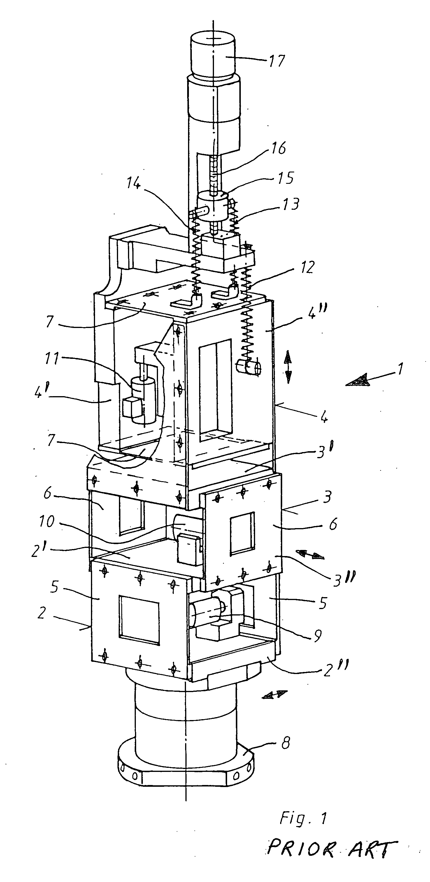
[0020] Referring now in detail to the drawings, FIG. 1 shows a measuring scanning head 1, as it is known according to the state of the art. The scanning head 1 has three scanning head rockers 2, 3, 4. Scanning head rockers 2, 3, 4 allow deflection of the scanning head in the x, y und z direction. For this purpose, the scanning head rockers have a fixed part 2′, 3′, 4′ and a movable part 2″, 3″, 4″, relative to the fixed parts, in each instance. The fixed parts 2′, 3′, 4′ and the movable parts 2″, 3″, 4″ are connected with one another by way of spring plates 5, 6, 7, so as to be displaceable relative to one another, in each instance.

[0021] A scanning pin (not shown) is attached to a feeler pickup 8. Each scanning head rocker has a path measurement system 9, 10, 11, in each instance. Scanning head 1 has weight equalization springs 12, 13, 14 that are connected with a spindle nut 15. A spindle 16 is driven by a motor 17, in order to move the spindle nut.

[0022]FIG. 2 shows a damping d...


PUM


Abstract

A scanning head of the measuring type for a coordinate measurement system, has a fixed part, at least one part that is displaceable relative to the fixed part, and at least one damping device for damping vibrations that occur. The at least one damping device is configured as an electric motor, which is connected with at least one negative ohmic resistor.

Description

BACKGROUND OF THE INVENTION [0001] The invention relates to a scanning head of the measuring type for a coordinate measuring device. These scanning heads consist of a fixed part that is connected with a device that can freely move and position the scanning head in three spatial dimensions, within a defined measurement volume, usually a so-called coordinate measurement device, as well as of three parts that are movable with regard to the fixed part. The movable parts are frequently configured as rockers with a parallel spring plate guide, which allows precise guidance in one spatial direction. The movement directions are usually disposed orthogonal to one another, and all of the other degrees of freedom are set. The movement directions of the three rockers build on one another kinematically, so that the last rocker of the kinematic chain is freely movable within a movement play space in the form of a cube having an edge length of typically a few millimeters. Furthermore, re-set eleme...

Claims


Application Information

Patent Timeline
IPC IPC(8): G01B5/00
CPCG01B7/012
Inventor MULLER, HANS-JURGEN
Owner HEXAGON METROLOGY GMBH
Why Eureka
Eureka Blog
Learn More