
Combined chip/heat-dissipating metal plate and method for manufacturing the same

a heat-dissipating metal plate and metal plate technology, which is applied in semiconductor/solid-state device testing/measurement, lighting and heating apparatus, instruments, etc., can solve the problems of heat-dissipating metal plate b>11/b> having poor compression strength in the radial direction, high compression strength and poor tension strength of chips, etc., to achieve improved compression strength and improve tensile strength

Inactive Publication Date: 2006-06-08
ARIMA OPTOELECTRONICS
View PDF7 Cites 0 Cited by
  • Summary
  • Abstract
  • Description
  • Claims
  • Application Information

AI Technical Summary

Benefits of technology

[0007] An objective of the present invention is to provide a combined chip / heat-dissipating metal plate with improved tensile strength and improved compression strength while providing a heat-dissipating effect.

Problems solved by technology

Such a chip has high compression strength and poor tension strength in the radial direction.
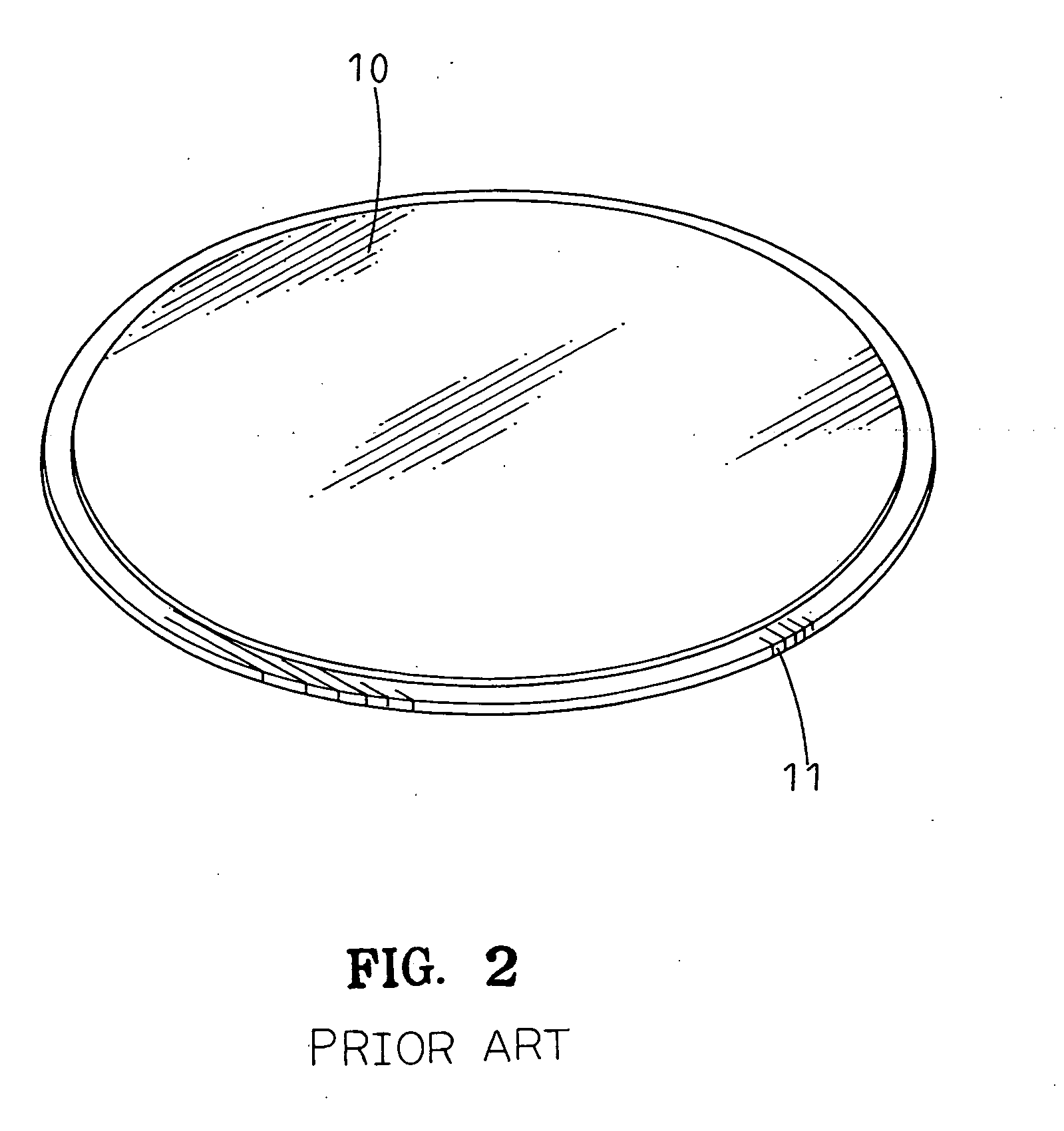
However, the heat-dissipating metal plate 11 has poor compression strength in the radial direction.
The combined chip / heat-dissipating metal plate is unstable and thus may adversely affect the subsequent cutting.

Method used


Image

  • Combined chip/heat-dissipating metal plate and method for manufacturing the same
  • Combined chip/heat-dissipating metal plate and method for manufacturing the same
  • Combined chip/heat-dissipating metal plate and method for manufacturing the same

Examples


Embodiment Construction

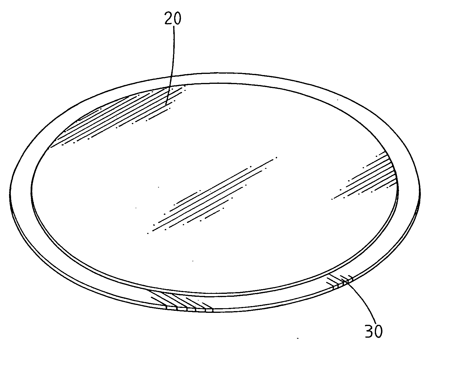
[0021] Referring to FIG. 3, a heat-dissipating metal plate 30 is bonded to a side of the chip 20 a chip for high-performance, high-brightness LEDs or high-frequency memories, forming a combined chip / heat-dissipating metal plate in accordance with the present invention. The chip 20 is made of gallium nitride, gallium arsenide, or silicon and has a thickness smaller than 0.1 mm. The heat-dissipating metal plate 30 is made of copper or aluminum and has a thickness smaller than 0.15 mm. A plurality of tiny balls are provided on the side of the chip 20 or adhesive is applied to the side of the chip 20. Next, the chip 20 and the heat-dissipating metal plate 30 are bonded together by applying pressure and heat.

[0022] It is noted that the heat-dissipating metal plate 30 is stretched before bonding with the chip 20. FIG. 4 illustrates a schematic block diagram illustrating a method for manufacturing the combined chip / heat-dissipating metal plate in accordance with the present invention. FIG...


PUM

PropertyMeasurementUnit
thicknessaaaaaaaaaa
thicknessaaaaaaaaaa
thicknessaaaaaaaaaa

Abstract

A combined chip / heat-dissipating metal plate includes a chip and a heat-dissipating metal plate bonded to a side of the chip, wherein the heat-dissipating metal plate is in a stretched state. The heat-dissipating metal plate is stretched before bonding the chip. Preferably, the stretched heat-dissipating metal plate has a thickness smaller than that of the heat-dissipating metal plate before stretching by not more than 20%. The chip has good compression strength in the radial direction and the heat-dissipating metal plate has higher tensile strength after being stretched and taking shape, providing a more stable structure and avoiding damage to the chip due to radially outward tension. The combined chip / heat-dissipating metal plate thus obtained is more stable and thus benefits the subsequent cutting by a laser cutting apparatus.

Description

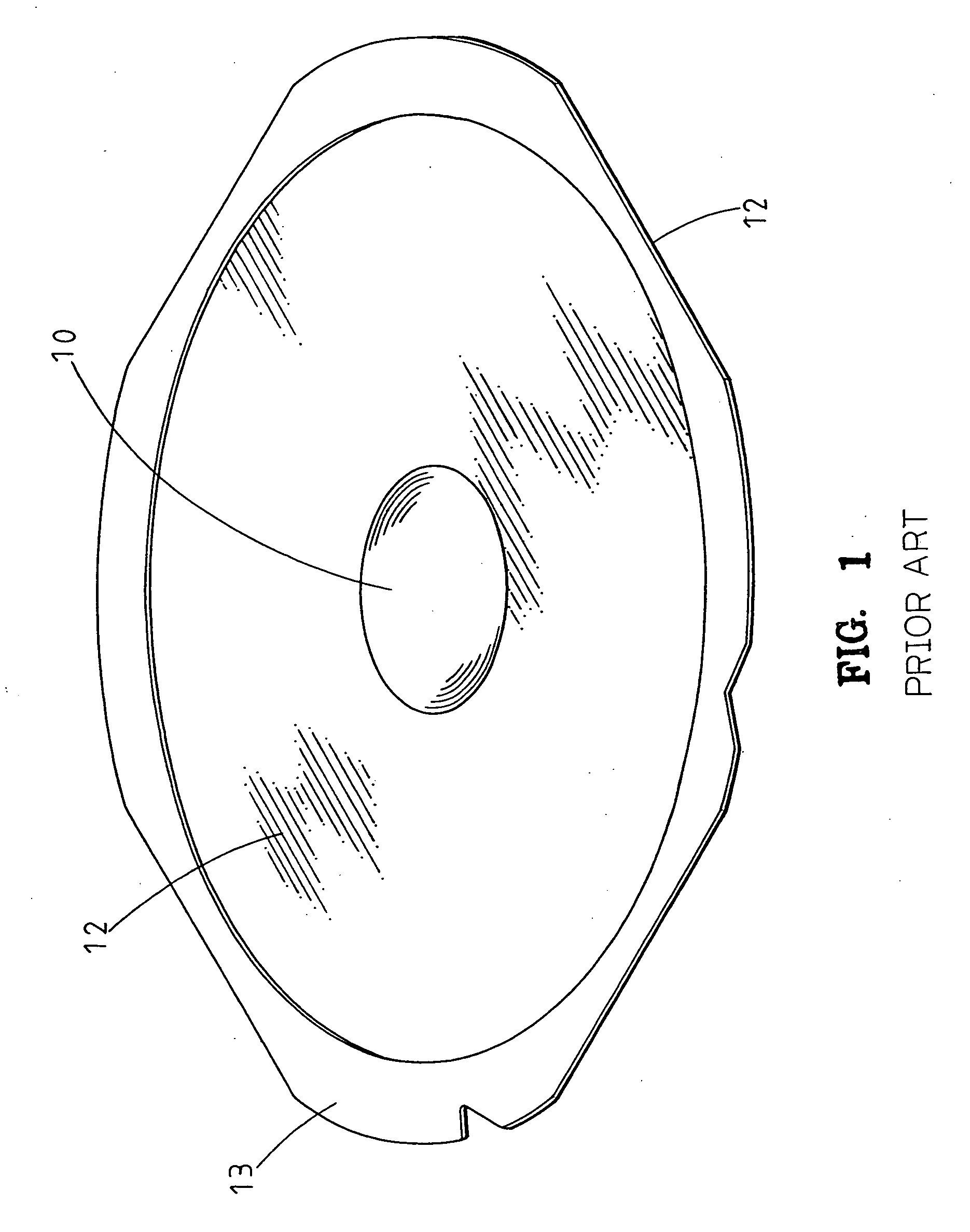
BACKGROUND OF THE INVENTION [0001] 1. Field of the Invention [0002] The present invention relates to a combined chip / heat-dissipating metal plate. In particular, the present invention relates to a combined chip / heat-dissipating metal plate providing a heat-dissipating effect when the chip is cut by a laser cutting device. The present invention also relates to a method for manufacturing the chip / heat-dissipating metal plate. [0003] 2. Description of the Related Art [0004] In current procedures for manufacturing light-emitting diodes (LEDs) and memories, numerous densely arrayed crystallite units are produced on a chip, and a laser cutting apparatus is used to cut the crystalline units into numerous crystallites. A typical chip includes an electrode layer, an epilayer (or epitaxy layer), and a gem layer. Before the laser cutting procedure, as show in FIG. 1, a chip 10 is adhered on a central area of an upper face of a see-through plastic film 12 placed on a working table of a laser cu...

Claims


Application Information

Patent Timeline
Patent Type & Authority Applications(United States)
IPC IPC(8): H05K7/20
CPCH01L23/142H01L23/3735H01L23/492H01L2924/0002Y10T29/49181Y10T29/49151Y10T29/4913Y10T29/49135Y10T29/49002Y10T29/49117H01L2924/00
Inventor HSU, CHIH-MING
Owner ARIMA OPTOELECTRONICS
Learn More