
Method and system for combining multiple laser beams using transmission holographic methodologies

a technology of transmission holographic and laser beam, which is applied in the direction of laser details, instruments, optical resonator shape and construction, etc., can solve the problems of much stricter incident angle and wavelength requirements, and achieve the effects of low cost, high diffraction efficiency and stable over tim

Inactive Publication Date: 2006-05-25
SHAHRIAR SELIMM
View PDF2 Cites 39 Cited by
  • Summary
  • Abstract
  • Description
  • Claims
  • Application Information

AI Technical Summary

Benefits of technology

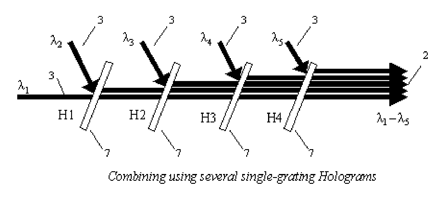
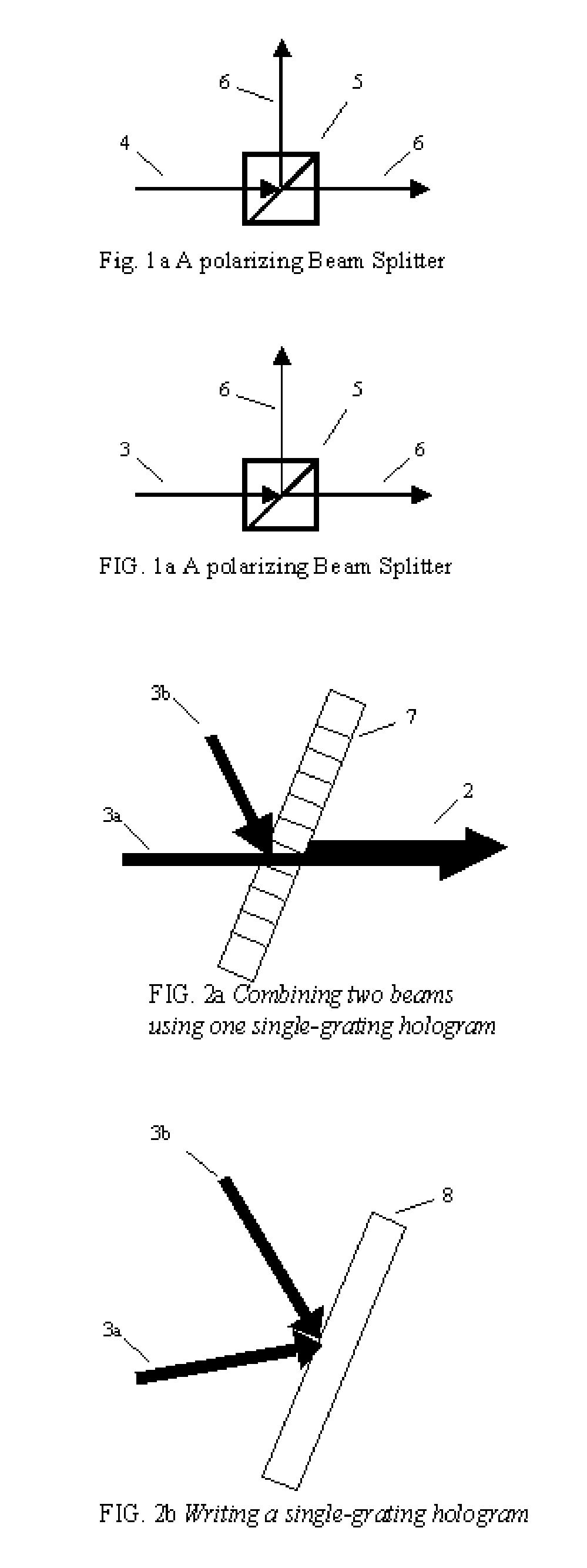
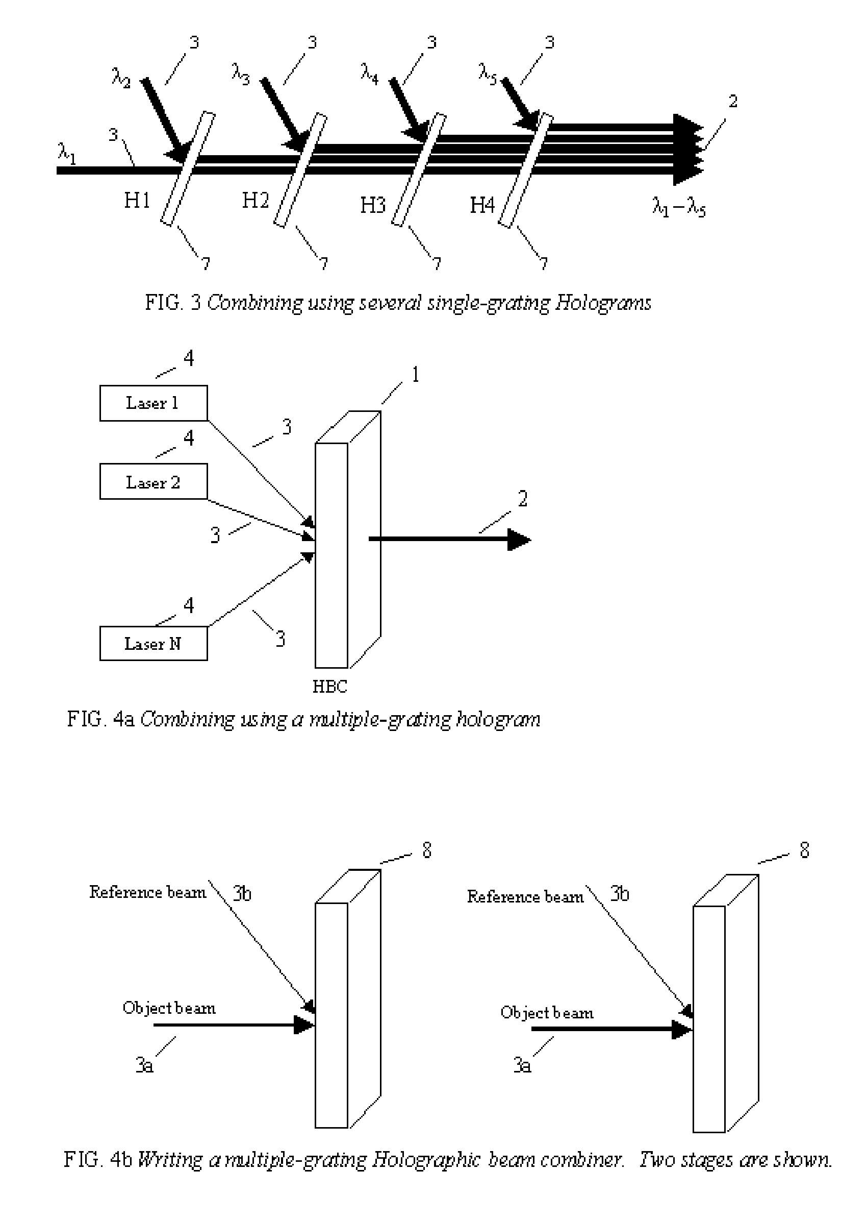
[0023] Beam combining can also accomplished using multiple-grating holograms. This method reduces the number of optical components used in the combining and also reduces the fresnel reflections losses. However, it also has much stricter incident angle and wavelength requirements. The basic concept used in combining is illustrated in FIG. 4a. Here, several beams 3 are combined using a single optical component known as the multiple-grating hologram 1 or a Holographic Beam Combiner. The hologram contains several gratings, each one diffracting one of the beams to be collinear as is illustrated. Such a hologram can be recorded by writing several holographic gratings into a recording material as illustrated in FIG. 4b. Each grating must be recorded individually, and the angles must be carefully chosen so that the diffracted beams are all directed along the same path.
[0025] The present invention relates to combining lasers that can be coherent (of the same wavelength) or incoherent (of different wavelengths) in a manner that is superior to alternative techniques using blazed gratings and other techniques. For coherent combinations, the input lasers have to be degenerate in frequency. For incoherent combinations, the input lasers are non-degenerate, differing in wavelengths by Δλ, which is dependent on the thickness of the holographic recording media. The ability to combine large numbers of coherent and incoherent lasers allows constructing optical power sources made up of numerous low powers, low cost semiconductor lasers that find applications in civilian, military and space applications, telecommunications and a wide range of industrial applications.
[0027] Many photopolymers may be utilized for storing holographic images, and the novel writing and reading techniques described herein will work with other materials. For purposes of disclosing this invention, the specific photopolymer discussed below is used. The material that is described in this invention application utilizes quinone-doped polymethyl methacrylate (PMMA) with a material parameter corresponding to the maximum index modulation (M# 20) that has efficiencies greater than 90% in each beam. This polymeric material uses a novel principle of “polymer with diffusion amplification”, or PDA. The material can readily withstand power intensities of up to 180 W / sq. cm without a drop in efficiency. This is the equivalent to being able to transfer 111 Kwatt of radiated laser energy utilizing a PMMA delivery geometry with an area of an 8½ by 11 inch sheet of paper. The HBC is scalable and the area the size of nine 8½ by 11 inch sheets of paper (841.5 sq. inches) will have the ability to transfer 1 Mw of laser power without a drop in efficiency. The energy transfer system is scalable and higher levels of power transfer are possible so long as the power intensities of the PDA material are not exceeded.
[0030] To reach laser power levels of tens, hundreds, or thousands of watts of power output and higher, large numbers of low cost, low power semiconductor lasers may be used. The most effective means for combining them is to use cascading of two or more stages of combined laser sources and groups of combined laser sources. This method of cascading is illustrated in FIG. 11. The cascading shown here is essentially an extension of the multiple-grating beam combining as previously described. Here, several beams 3 that are already combined beams can be further combined. For example, by starting with an easily manageable number of 25 lasers in the first stage, feeding into a second stage of say 20 first stage units and a third stage of 20 second stage units, a combined output with the total of 25×20×20 or 10,000 lasers sources, less minor losses contributed by holographic material. If each laser has a power of 50 mw, the resultant output will be 10,000×0.05×0.9×0.9×0.9 or 364.5 W, assuming an efficiency of 0.9 for each cascaded stage.

Problems solved by technology

However, it also has much stricter incident angle and wavelength requirements.

Method used


Image

  • Method and system for combining multiple laser beams using transmission holographic methodologies
  • Method and system for combining multiple laser beams using transmission holographic methodologies
  • Method and system for combining multiple laser beams using transmission holographic methodologies

Examples


Embodiment Construction

[0044] The following description is presented to enable one of ordinary skill in the art to make and use the invention and is provided in the context of a patent application and its requirements. Various modifications to the preferred embodiments will be readily apparent to those skilled in the art and the generic principles herein may be applied to other embodiments. Thus, the present invention is not intended to be limited to the embodiments shown, but is to be accorded the widest scope consistent with the principles and features described herein.

[0045] This description will focus on combining using multiple-grating holograms, although it should be noticed that this also encompasses the methods for combining using single-grating holograms.

[0046] In order to fully understand the embodiments of this invention, it is first necessary to describe the technique for writing and reading a single holograms onto a holographic substrate and then in writing multiple holograms onto the same ...


PUM


Abstract

The Holographic Beam Combiner, (HBC), is used to combine the output from many lasers into a single-aperture, diffraction-limited beam. The HBC is based on the storage of multiple holographic gratings in the same spatial location. By using a photopolymer material such as quinone-doped polymethyl methacrylate (PMMA) that uses a novel principle of “polymer with diffusion amplification” (PDA), it is possible to combine a large number (N) of diode lasers, with an output intensity and brightness 0.9 N times as much as those of the combined outputs of individual N lasers. The HBC will be a small, inexpensive to manufacture, and lightweight optical element. The basic idea of the HBC is to construct multiple holograms onto a recording material, with each hologram using a reference beam incident at a different angle, but keeping the object beam at a fixed position. When illuminated by a single read beam at an angle matching one of the reference beams, a diffracted beam is produced in the fixed direction of the object beam. When multiple read beams, matching the multiple reference beams are used simultaneously, all the beams can be made to diffract in the same direction, under certain conditions that depend on the degree of mutual coherence between the input beams.

Description

GOVERNMENT INTERESTS [0001] GOVERNMENT RIGHTS STATEMENT: This invention was made with government support under contract F29601-00-C-0084 and F29601-01-C-0015 awarded by the US Air Force. The government has certain rights in the invention.Reference Cited [0002]U.S. PATENT DOCUMENTS6,263,126Jul. 17, 2001Cao6,256,321Jul. 3, 2001Kobayashi6,005,8611Feb. 21, 1999Humpleman6,256,308 B1Jul. 3, 2001Carlsson5,999,5181Feb. 7, 1999Nattkemper et a.l.6,043,914Mar. 28, 2000Cook et al.6,263,130 B1Jul. 17, 2001Barnard6,211,978 B!Apr. 3, 2001WojtunikRELATED U.S. APPLICATIONS DATA [0003] Provisional application No. 60 / 563,824 OTHER PUBLICATIONS [0004] Coupled Wave Theory for Thick Hologram Gratings; The Bell System Technical Journal: Herwig Kogelnik, Vol. 48, No. 9, November 1969 [0005] Cascaded Coupled Mach-Zehner Channel Dropping Filters for Wavelength-Division-Multiplexed Wavelength-Division Multiplexed Optical Systems; Journal of Lightwave Technology: M. Kuznetsov, Vol. 12, No. 2, February 1994 [00...

Claims


Application Information

Patent Timeline
Patent Type & Authority Applications(United States)
IPC IPC(8): H01S3/13H01S3/08
CPCG02B5/32G02B27/0944G02B27/1086G02B27/1093H01S5/4012H01S5/4025H01S5/4056H01S5/4062G02B19/0057G02B19/0009G02B19/0028G03H1/0248G03H1/28G03H2001/0439
Inventor DONOGHUE, JOHNANDREWS, MARK
Owner SHAHRIAR SELIMM
Learn More