Quadri-filar helix antenna structure

a quadrifilar helix and antenna technology, applied in the direction of antenna details, non-resonant long antennas, antennas, etc., can solve the problems of insufficient robustness, inability to easily modify to overcome this difficulty without a performance penalty, and patch antennas tend to have poor gain at low angles of elevation, so as to reduce time and manpower, reduce component size, and simplify manufacturing process

Inactive Publication Date: 2006-05-18
TAIWAN GREEN POINT ENTERPRISE
View PDF10 Cites 4 Cited by
  • Summary
  • Abstract
  • Description
  • Claims
  • Application Information

AI Technical Summary

Benefits of technology

[0011] In view of the shortcomings of the prior art, the inventor of the present invention based on years of experience in the related field to conduct extensive research and development to overcome the foregoing shortcomings of the traditional quadri-filar antenna being too large and requiring a very complicated manufacturing process and find a solution for the improvement, and finally invented a quadri-filar helix antenna structure, and used a silkscreen printing method to effectively simplify the manufacturing process and reduce the time and manpower required for the manufacturing process and achieve the objectives of reducing the component size to make the antenna “light, thin, short and compact” as well as “good quality with a low price”.
[0012] Therefore, it is one of the objectives of the present invention to provide a quadri-filar spiral antenna structure, which comprises a cylindrical body made of a dielectric material and four radiating metal plates disposed on a distal end surface of the cylindrical body, and each radiating metal plate is extended along the radial direction of the center of the cylindrical body to its periphery, and then extended along the radial direction in a spiral course on the circumferential surface of the cylindrical body to its periphery on the other end. On a distal end surface of the cylindrical body, the ends of every two adjacent radiating metal plates are coupled with each other to constitute two sets of antenna structures, and a penetrating hole is disposed at the central position of the cylindrical body, and the penetrating hole is precisely embedded into a coaxial cable, and a shield cable disposed at the periphery on one end of the coaxial cable is coupled to an end of another set of antenna structure. Therefore, the antenna so formed no longer requires the “Balun” but only uses the four radiating metal plates surrounding the cylindrical body to about a quarter of its wavelength for achieving the purpose of receiving satellite signals, not only reducing the overall antenna volume, but also greatly lowering its production and transportation costs.

Problems solved by technology

However, one of the disadvantages of such three-dimensional antenna is that in certain applications, it is insufficiently robust, and cannot easily be modified to overcome this difficulty without a performance penalty.
This kind of patch antennas comes with thin sheet radiating metal plates attached on an insulating material of the aircraft fuselage, but such patch antenna tends to have poor gain at low angles of elevation.
This technique is expensive, not only due to the numbers of batch antennas required, but also due to the difficulty of combining the received signals and integrating all these batch antennas.
However, the manufacturing process involved is more complicated and requires copper plating, lithography, etching and laser trimming processes.

Method used


Image

  • Quadri-filar helix antenna structure
  • Quadri-filar helix antenna structure
  • Quadri-filar helix antenna structure

Examples


Embodiment Construction

[0023] To make it easier for our examiner to understand the objective of the invention, its structure, innovative features, and performance, we use a preferred embodiment together with the attached drawings for the detailed description of the invention.

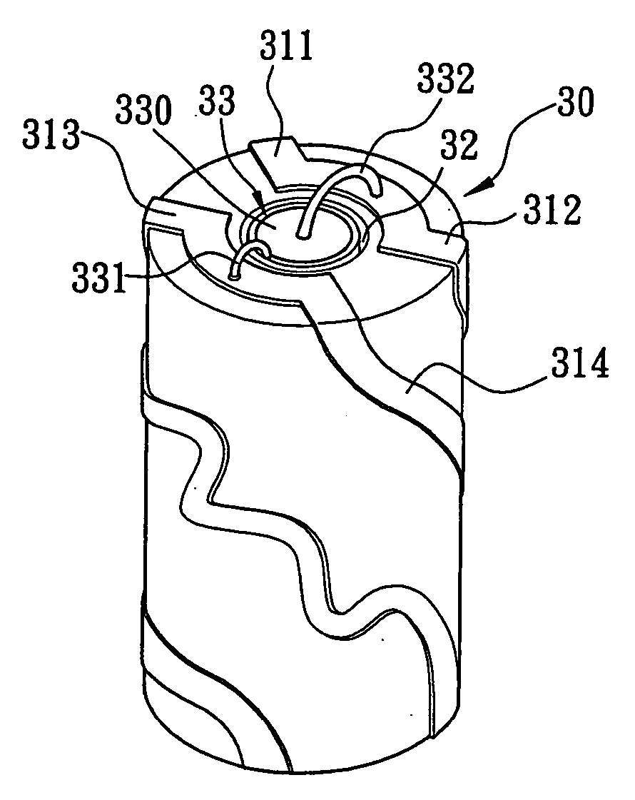
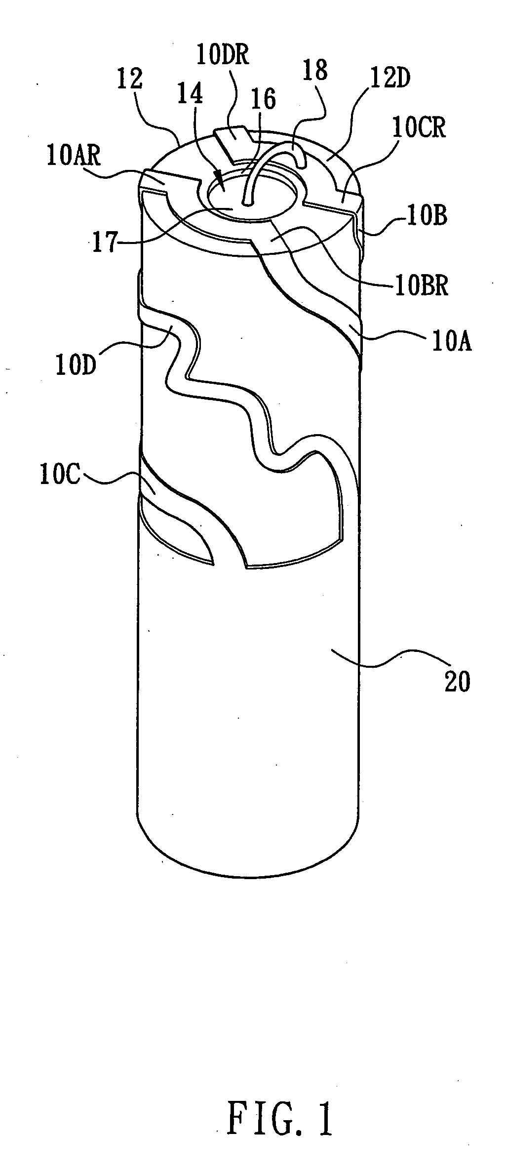
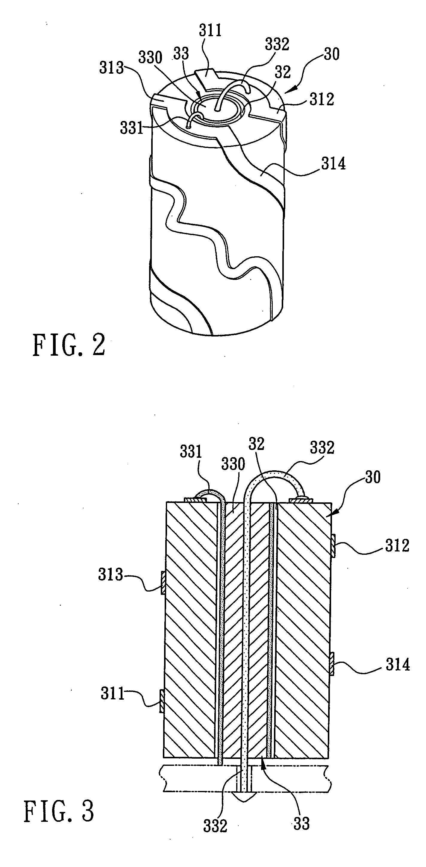
[0024] Please refer to FIGS. 2, 4 and 6 for a quadri-filar helix antenna structure in accordance with the present invention. The quadri-filar helix antenna structure comprises a cylindrical body 30, 40, 50 being made of a dielectric material (which could be a ceramic material or a polymer material), and four radiating metal plates 311, 312, 313314, 411, 412, 413, 414, 511, 512, 513, 514 being disposed at a distal end surface of the cylindrical body 30, 40, 50, and each radiating metal plate 311, 312, 313314, 411, 412, 413, 414, 511, 512, 513, 514 is extended along a radial direction of the center of the cylindrical body 30, 40, 50 to its periphery, and then extended along a spiral course on the circumferential surface of the cylindri...


PUM


Abstract

The present invention discloses a quadri-filar helix antenna structure, which comprises a cylindrical body made of a dielectric material with a relative dielectric constant εr greater than 4, and four radiating metal plates disposed on a distal end surface of the cylindrical body and extended along the radial direction of the center of the cylindrical body to its periphery and then along the radial direction in a spiral course on the circumferential surface thereof to its periphery on the other end respectively, wherein the ends of every two adjacent radiating metal plates are coupled with each other to constitute two sets of antenna structures, a penetrating hole is disposed at the central position of the cylindrical body and is precisely embedded into a coaxial cable, and a shield cable disposed at the periphery on one end of the coaxial cable is coupled to an end of another set of antenna structure. Therefore, the antenna not only reduces the overall volume, but also greatly lowers its production costs.

Description

BACKGROUND OF THE INVENTION [0001] 1. Field of the Invention [0002] The present invention relates to an antenna structure, more particularly to a quadri-filar helix antenna structure that can reduces the overall antenna size and greatly lowers its production and transportation costs. [0003] 2. Description of the Related Art [0004] In recent years, as the wireless communication industry is blooming, the service of the satellite personal communication network (SPCN) available in the market gains more attentions, particularly the applications of handheld terminals (HHT). Therefore, people all over the world can communicate with each other by the handheld terminal through the satellite personal communication network, or the location of the handheld terminal holder can be located in a fast manner through the satellite personal communication network as to improve work efficiency and avoid unnecessary wastes of manpower, time and resources, and all these depends on the structure and design...

Claims


Application Information

Patent Timeline
Patent Type & Authority Applications(United States)
IPC IPC(8): H01Q1/36H01Q1/38H01Q11/08
CPCH01Q1/362H01Q1/38H01Q11/08
Inventor YANG, PEI-LINHUNG, CHIA-CHUNCHEN, CHUN-HAOLEE, TING-CHUN
Owner TAIWAN GREEN POINT ENTERPRISE
Why Eureka
Try Eureka