Eureka AIR delivers breakthrough ideas for toughest innovation challenges, trusted by R&D personnel around the world.

Apparatus and method for the deposition of silicon nitride films

Inactive Publication Date: 2006-05-18
APPLIED MATERIALS INC
View PDF99 Cites 259 Cited by
  • Summary
  • Abstract
  • Description
  • Claims
  • Application Information

AI Technical Summary

Benefits of technology

[0010] The present invention comprises a method and apparatus for a CVD chamber that provides uniform heat distribution; uniform distribution of process chemicals, and minimization of residue in the chamber. Minimizing residue in the CVD chamber includes improvements to chamber and process kit surfaces, remote plasma generation, gas delivery and divert lines, isolation and throttle valves, and exhaust system. The improvements include a processing chamber comprising a chamber body, a base, and a chamber lid defining a processing region, a substrate support disposed in the processing region, a gas delivery system mounted on a chamber lid, the gas delivery system comprising an adapter ring and one or more blocker plates that define a gas mixing region, and a face plate fastened to the adapter ring, an exhaust system mounted at the base, a heating element positioned to heat the adapter ring, and a heating element positioned to heat a portion of the exhaust system. Optionally, a continuous purge through the remote plasma generator may be selected.

Problems solved by technology

As new process chemistries are introduced for low temperature deposition, for example, a liquid silicon source such as bis(tertiary butylamino)silane, residue due to condensation and byproduct deposition becomes a chamber cleaning challenge.

Method used


Image

  • Apparatus and method for the deposition of silicon nitride films
  • Apparatus and method for the deposition of silicon nitride films
  • Apparatus and method for the deposition of silicon nitride films

Examples


Embodiment Construction

[0023] Embodiments of the invention provide apparatus and methods for depositing a layer on a substrate. The hardware discussion including illustrative figures of an embodiment is presented first. An explanation of process modifications and test results follows the hardware discussion. Chemical vapor deposition (CVD), sub-atmospheric chemical vapor deposition (SACVD), rapid thermal chemical vapor deposition (RTCVD), and low pressure chemical vapor deposition (LPCVD) are all deposition methods that may benefit from the following apparatus and process modifications. Examples of CVD processing chambers that may utilize some of the embodiments of this apparatus and process include SiNgen™, SiNgen-Plus™, and FlexStar™ chambers which are commercially available from Applied Materials, Inc. of Santa Clara, Calif.

Apparatus

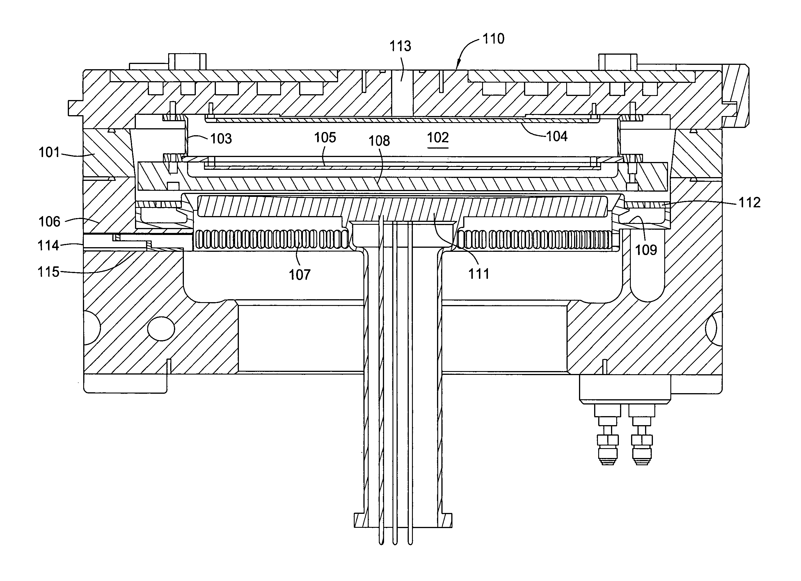
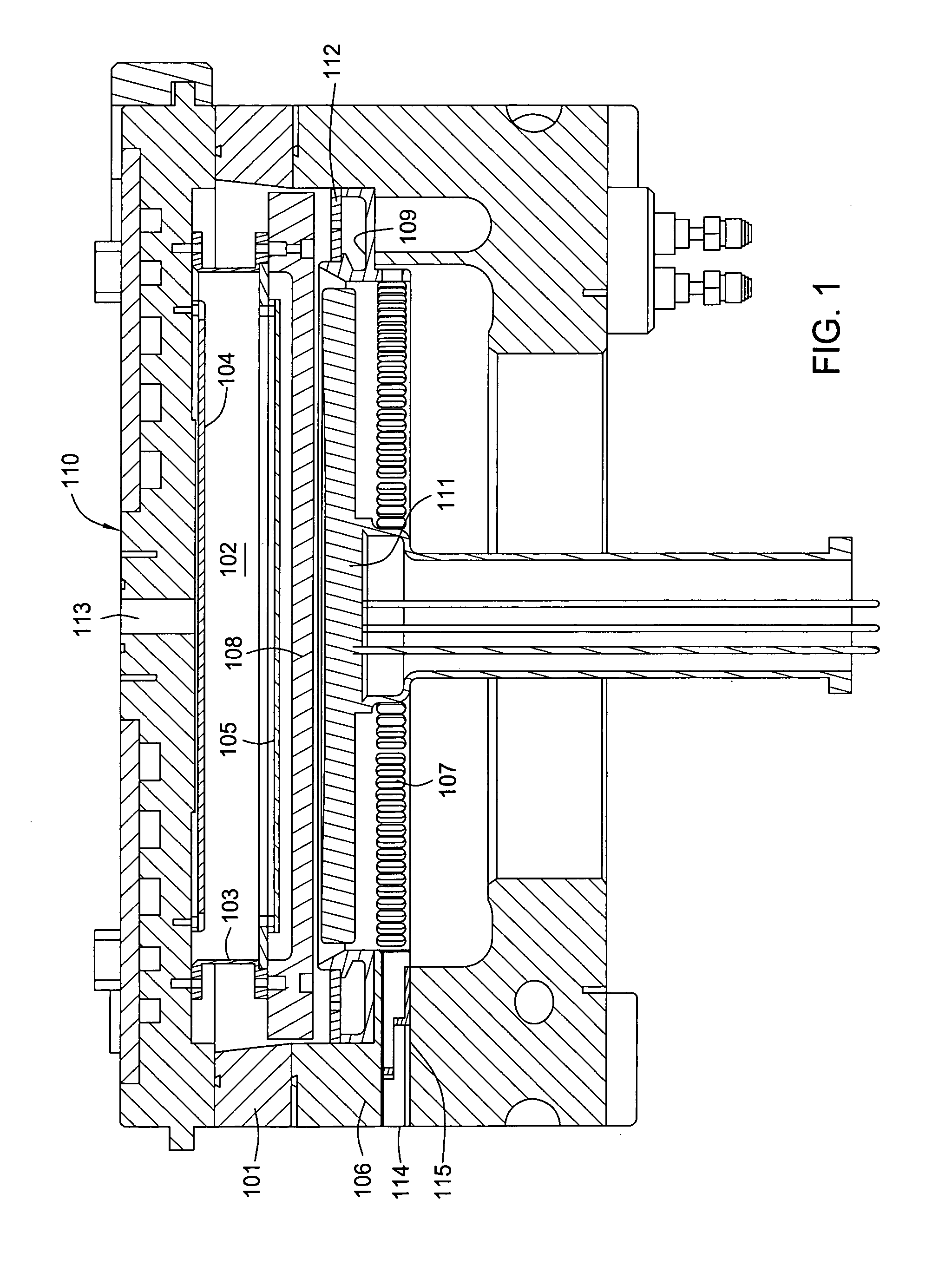
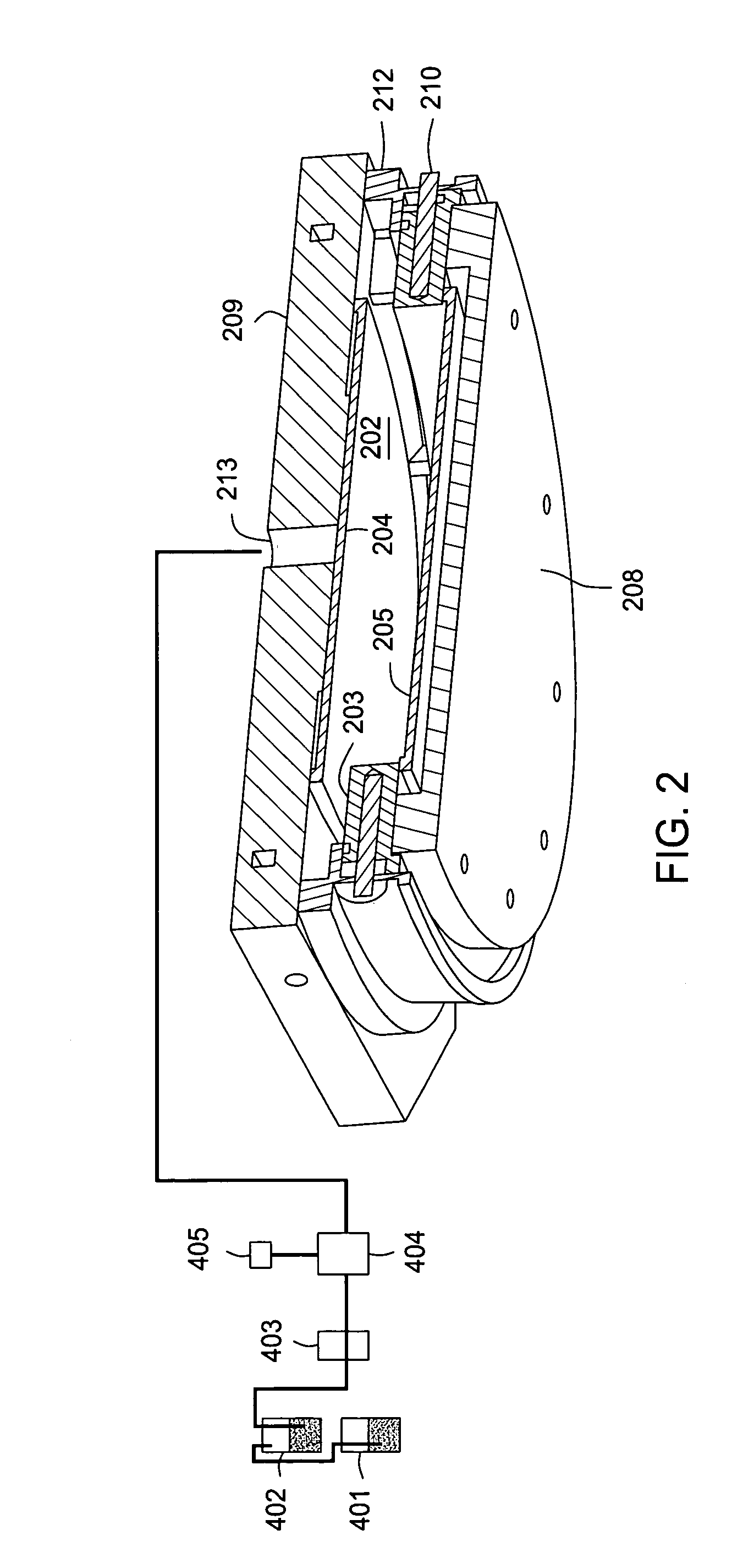
[0024]FIG. 1 is a cross sectional view of an embodiment of a single wafer CVD processing chamber having a substantially cylindrical wall 106 closed at the upper end by a...


PUM

PropertyMeasurementUnit
Fractionaaaaaaaaaa
Lengthaaaaaaaaaa
Lengthaaaaaaaaaa

Abstract

A method and apparatus for a chemical vapor deposition (CVD) chamber provides uniform heat distribution, uniform distribution of process chemicals in the CVD chamber, and minimization of by-product and condensate residue in the chamber. The improvements include a processing chamber comprising a chamber body, a base, and a chamber lid defining a processing region, a substrate support disposed in the processing region, a gas delivery system mounted on a chamber lid, the gas delivery system comprising an adapter ring and two blocker plates that define a gas mixing region, and a face plate fastened to the adapter ring, an exhaust system mounted at the base, a heating element positioned to heat the adapter ring; and a heating element positioned to heat a portion of the exhaust system.

Description

CROSS-REFERENCE TO RELATED APPLICATIONS [0001] This application is a continuation in part of U.S. patent application Ser. No. 10 / 911,208, (APPM / 007395) filed Aug. 4, 2004, which claims benefit of U.S. Provisional Patent Application Ser. No. 60 / 525,241 (APPM / 007395L), filed Nov. 25, 2003, which applications are herein incorporated by reference.BACKGROUND OF THE INVENTION [0002] 1. Field of the Invention [0003] Embodiments of the present invention generally relate to substrate processing. More particularly, the invention relates to chemical vapor deposition chambers and processes. [0004] 1. Description of the Related Art [0005] Chemical vapor deposited (CVD) films are used to form layers of materials within integrated circuits. CVD films are used as insulators, diffusion sources, diffusion and implantation masks, spacers, and final passivation layers. The films are often deposited in chambers that are designed with specific heat and mass transfer characteristics to optimize the deposi...

Claims


Application Information

Patent Timeline
IPC IPC(8): C23C16/00C23C16/34C23C16/44C23C16/455
CPCC23C16/345C23C16/4412C23C16/45565C23C16/4557C23C16/34C23C16/455H01L21/0262C23C16/52H01L21/67207
Inventor SMITH, JACOB W.SEUTTER, SEAN M.IYER, R. SURYANARAYANANTRAN, BINHTAM, ALEXANDERWILSON, JAMES K.
Owner APPLIED MATERIALS INC
Why Eureka
Eureka Blog
Learn More