
Methods of making a current-perpendicular-to-the-planes (CPP) type sensor by ion milling to the spacer layer using a mask without undercuts

a technology of current perpendicular to the plane and ion milling, which is applied in the direction of manufacturing head surfaces, instruments, manufacturing tools, etc., can solve the problems of re-deposition of electrically conducting materials, re-circuited pinned ferromagnetic layer and free ferromagnetic layer, and conventional masks used during ion milling that do not provide a well-defined track width (tw), so as to improve cpp type sensor performance performance and improv

Inactive Publication Date: 2006-05-04
HITACHI GLOBAL STORAGE TECH NETHERLANDS BV
View PDF15 Cites 19 Cited by
  • Summary
  • Abstract
  • Description
  • Claims
  • Application Information

AI Technical Summary

Benefits of technology

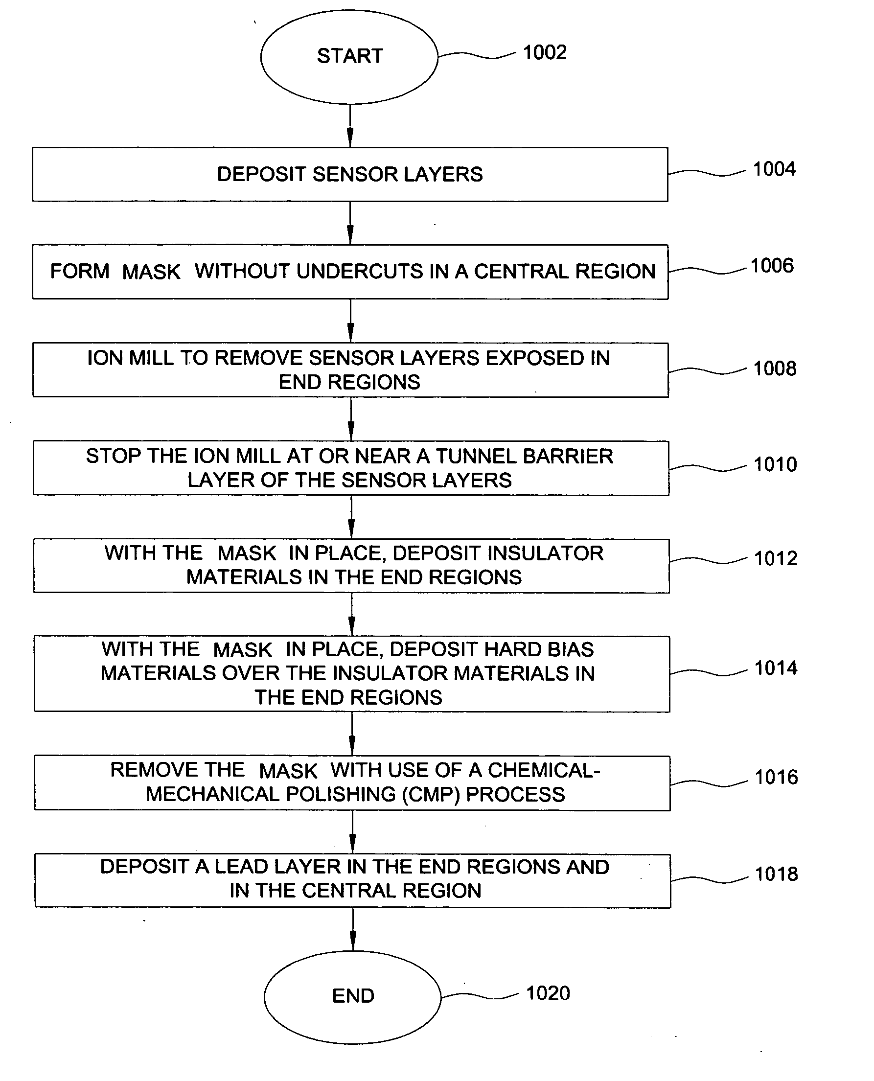
[0011] Methods for use in forming current-perpendicular-to-the-planes (CPP) type sensors, including CPP giant magnetoresistance (GMR) type and CPP magnetic tunnel junction (MTJ) type sensors are disclosed. In one particular example, a plurality of CPP type sensor layers are formed over a wafer and a mask without undercuts is formed over the plurality of CPP type sensor layers in a central region. With the mask without undercuts in place, an ion milling process is started to remove CPP type sensor layer materials left exposed by the mask without undercuts in end regions which surround the central region. The ion milling process is stopped at or near a spacer layer of the CPP type sensor layers. Insulator materials are then deposited in the end regions where the CPP type sensor layer materials were removed, followed by hard bias materials over the insulator materials. The mask without undercuts is then removed through use of a chemical-mechanical polishing (CMP) assisted lift-off process, which also planarizes the top surface. Typical sensor techniques of the art are then performed to complete manufacture of the CPP type sensor. Using the mask without undercuts enables the removal of a freelayer of the plurality of CPP type sensor layers down to the spacer layer or beyond to form the CPP type sensor with sharp and steep sidewalls which is not possible with conventional mask structures. The act of stopping the ion milling process at or near the spacer layer reduces a likelihood of electrical shorting around side edges of the spacer layer. This unique combination thereby results in improved CPP type sensor performance through improved amplitude and stability.

Problems solved by technology

This ion milling process, while necessary to form the sensor, may result in the re-deposition of electrically conducting material (such as metal particles or contamination) along the sides of the spacer layer such that the pinned ferromagnetic layer and the free ferromagnetic layer become short-circuited.
Also, conventional masks used during the ion milling do not provide for a well-defined trackwidth (TW).

Method used


Image

  • Methods of making a current-perpendicular-to-the-planes (CPP) type sensor by ion milling to the spacer layer using a mask without undercuts
  • Methods of making a current-perpendicular-to-the-planes (CPP) type sensor by ion milling to the spacer layer using a mask without undercuts
  • Methods of making a current-perpendicular-to-the-planes (CPP) type sensor by ion milling to the spacer layer using a mask without undercuts

Examples


Embodiment Construction

[0030] Methods for use in forming current-perpendicular-to-the-planes (CPP) type sensors, including CPP giant magnetoresistance (GMR) type and CPP magnetic tunnel junction (MTJ) type sensors are disclosed. In one particular example, a plurality of CPP type sensor layers are formed over a wafer and a mask without undercuts is formed over the plurality of CPP type sensor layers in a central region. With the mask without undercuts in place, an ion milling process is started to remove CPP type sensor layer materials left exposed by the mask without undercuts in end regions which surround the central region. The ion milling process is stopped at or near a spacer layer of the CPP type sensor layers. Insulator materials are then deposited in the end regions where the CPP type sensor layer materials were removed, followed by hard bias materials over the insulator materials. The mask without undercuts is then removed through use of a chemical-mechanical polishing (CMP) assisted lift-off proc...


PUM

PropertyMeasurementUnit
nonmagneticaaaaaaaaaa
CPP giant magnetoresistiveaaaaaaaaaa
electrically conductiveaaaaaaaaaa

Abstract

Methods for use in forming current-perpendicular-to-the-planes (CPP) type sensors, including CPP giant magnetoresistance (GMR) type and CPP magnetic tunnel junction (MTJ) type sensors are disclosed. In one particular example, a plurality of CPP type sensor layers are formed over a wafer and a mask without undercuts is formed over the plurality of CPP type sensor layers in a central region. With the mask without undercuts in place, an ion milling process is started to remove CPP type sensor layer materials left exposed by the mask without undercuts in end regions which surround the central region. The ion milling process is stopped at or near a spacer layer of the CPP type sensor layers. Insulator materials are then deposited in the end regions where the CPP type sensor layer materials were removed, followed by hard bias materials over the insulator materials. The mask without undercuts is then removed through use of a chemical-mechanical polishing (CMP) assisted lift-off process, which also planarizes the top surface. Typical sensor techniques of the art are then performed to complete manufacture of the CPP type sensor. Using the mask without undercuts enables the removal of a freelayer of the plurality of CPP type sensor layers down to the spacer layer or beyond to form the CPP type sensor with sharp and steep sidewalls which is not possible with conventional mask structures. The act of stopping the ion milling process at or near the spacer layer reduces a likelihood of electrical shorting around side edges of the spacer layer. This unique combination thereby results in improved CPP type sensor performance through improved amplitude and stability.

Description

BACKGROUND [0001] 1. Field of the Technology [0002] The present invention relates generally to methods of making read sensors of the current-perpendicular-to-the-planes (CPP) giant magnetoresistive (GMR) type and the CPP magnetic tunnel junction (MTJ) type. [0003] 2. Description of the Related Art [0004] Computers often include auxiliary memory storage devices having media on which data can be written and from which data can be read for later use. A direct access storage device (disk drive) incorporating rotating magnetic disks are commonly used for storing data in magnetic form on the disk surfaces. Data is recorded on concentric, radially spaced tracks on the disk surfaces. Magnetic heads which include read sensors are then used to read data from the tracks on the disk surfaces. [0005] In high capacity disk drives, magnetoresistive (MR) read sensors, commonly referred to as MR heads, may be used to read data from a surface of a disk at greater linear densities than thin film induc...

Claims


Application Information

Patent Timeline
Patent Type & Authority Applications(United States)
IPC IPC(8): H01L21/00
CPCB82Y25/00G11B5/3163G11B5/3169Y10T29/49046Y10T29/49052Y10T29/49048Y10T29/49043G11B5/39G11B2005/3996G11B5/3909
Inventor PINARBASI, MUSTAFA M.
Owner HITACHI GLOBAL STORAGE TECH NETHERLANDS BV
Learn More