Illuminating apparatus, method for fabricating the same and display apparatus using the same
a technology of illumination apparatus and mounting plate, which is applied in the direction of lighting and heating apparatus, point-like light sources, instruments, etc., can solve the problems of reducing the yield rate of the plurality of light emitting diodes, increasing the mounting cost. , to achieve the effect of reducing the number of mounting spots, reducing the cost, and increasing the yield ra
- Summary
- Abstract
- Description
- Claims
- Application Information
AI Technical Summary
Benefits of technology
Problems solved by technology
Method used
Image
Examples
first embodiment
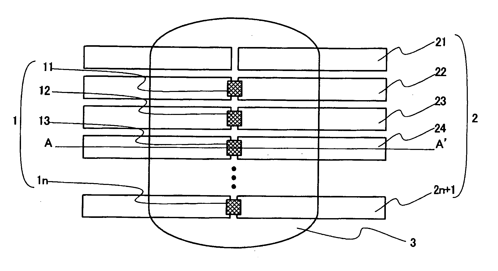
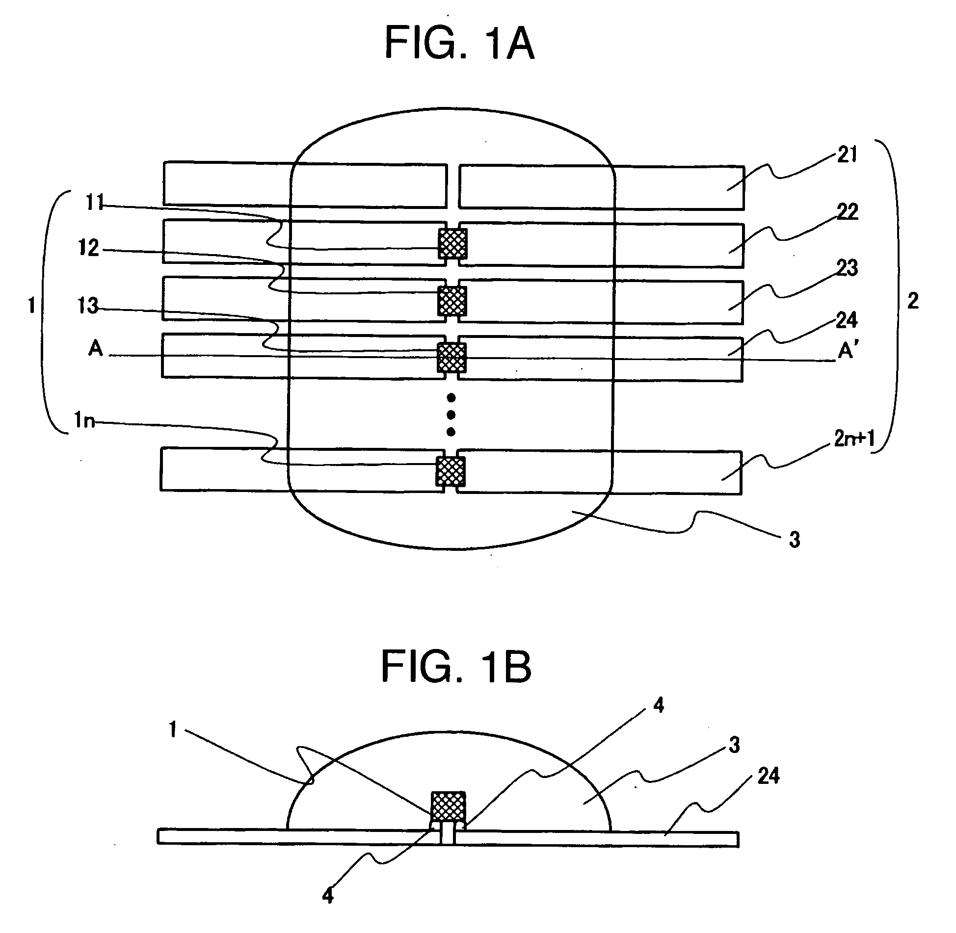
[0031]FIGS. 1A and 1B are diagrams for describing an illuminating apparatus according to a first embodiment of the present invention, where FIG. 1A shows a top plan view of the illuminating apparatus, and FIG. 1B shows a cross-sectional view taken along a line A-A′ in FIG. 1A. The illuminating apparatus of the first embodiment comprises N (N is an integer equal to or larger than one) light emitting diodes 1 (11-1n); (N+1) sets or more of lead frames 2 (21-2n+1); and a transparent sealer 3. FIG. 1 illustrates (N+1) sets of the lead frames 2. Each light emitting diode 1 is mounted on the lead frame 2 with solder 4. Then, the light emitting diodes 1 mounted on the lead frames 2 are sealed by the transparent sealer 3. In the first embodiment, the transparent sealer 3, and the light emitting diodes 1 and lead frames 2 sealed by the transparent sealer 3 are collectively referred to as a “module” which constitutes one unit. In FIG. 1, one module forms an illuminating apparatus.
[0032] In t...
second embodiment
[0044]FIG. 4 is a top plan view for describing an illuminating apparatus according to a second embodiment of the present invention. The illuminating apparatus of the second embodiment comprises N (N is an integer equal to or more than four) light emitting diodes 1, (2N−3) sets of lead frames 2, and a transparent sealer 3, where there are (N−3) sets of lead frames 2 which are not mounted with the light emitting diodes 1. FIG. 4 illustrates the illuminating apparatus which comprises five light emitting diodes (11, 12, 13, 14, 15) (N=5), and therefore seven sets of lead frames (21, 22, 23, 24, 25, 26, 27). In FIG. 4, the outermost lead frames 21, 27 are mounted with the light emitting diodes 11, 15, respectively, where they are mounted in an upper half area or a lower half area from the center lines (broken lines in FIG. 4) of the lead frames 21, 27, respectively. In addition, each of the light emitting diodes 12-14 mounted on the inner lead frames 22-26 straddles the center line of th...
third embodiment
[0052]FIG. 9 is a top plan view for describing an illuminating apparatus according to a third embodiment of the present invention, where three modules of the second embodiment described above are connected in series. Sets of lead frames, on which light emitting diodes of the modules 101, 102, 103 are mounted, are each composed of a series of lead frames which are connected in series.
[0053]FIG. 10 is a top plan view for describing a method of repairing the illuminating apparatus according to the third embodiment of the present invention. The illuminating apparatus of the third embodiment can be fabricated by similar steps to those in the first and second embodiments, and the illuminating apparatus can be formed as illustrated in FIG. 9 if all light emitting diodes are determined as conforming in the testing step. On the other hand, if any light emitting diode is determined as defective, a new light emitting diode can be mounted to make the illuminating apparatus conforming, as descr...
PUM
 Abstract
Description
Claims
Application Information
 - R&D
- Intellectual Property
- Life Sciences
- Materials
- Tech Scout
- Unparalleled Data Quality
- Higher Quality Content
- 60% Fewer Hallucinations
Browse by: Latest US Patents, China's latest patents, Technical Efficacy Thesaurus, Application Domain, Technology Topic, Popular Technical Reports.
© 2025 PatSnap. All rights reserved.Legal|Privacy policy|Modern Slavery Act Transparency Statement|Sitemap|About US| Contact US: help@patsnap.com


