
Energy conversion systems

a technology of energy conversion and energy, applied in the direction of dynamo-electric converter control, motor/generator/converter stopper, generator/motor, etc., can solve the problem of limiting applications to locations outside the earth's, and achieve the effect of reducing slippage and consuming a lot of power in that heating

Inactive Publication Date: 2006-04-20
CORREA PAULO N +1
View PDF10 Cites 6 Cited by
  • Summary
  • Abstract
  • Description
  • Claims
  • Application Information

AI Technical Summary

Benefits of technology

[0032] We have previously proposed the use of squirrel cage motors with capacitative splitting of phase to convert the damped wave (DW) output of plasma pulsers, but once a squirrel cage (SC) is introduced, the dampening effect which the nonferromagnetic copper cage exerts in being dragged by the revolving stator field is counteracted by the ferromagnetic cylinder of laminated iron, in which the copper cage is embedded, working to diminish the slip and bring the rotor to near synchronism. This is, in all likelihood, what limits SC motors to responding to the DC component of the DW impulse, and thus be limited to respond to fluxes of massbound charges. Historically, as we shall see, the obvious advantage of the SC servomotors lay in the fact that, in particular for 2-phase applications, they were far more efficient at performing work without evolution of heat. Indeed, if the eddy currents in the nonferromagnetic rotor are permitted to circulate in nonordered form, the rotor material and stator will heat up rapidly and consume much power in that heating. This is in fact considered to be a weakness of AC nonferromagnetic-rotor induction motors.

Problems solved by technology

For example, the sun is a natural source of such radiation, although interaction with the atmosphere means that it is largely unavailable at the earth's surface, limiting applications to locations outside of the earth's atmosphere.

Method used


Image

  • Energy conversion systems
  • Energy conversion systems
  • Energy conversion systems

Examples


Embodiment Construction

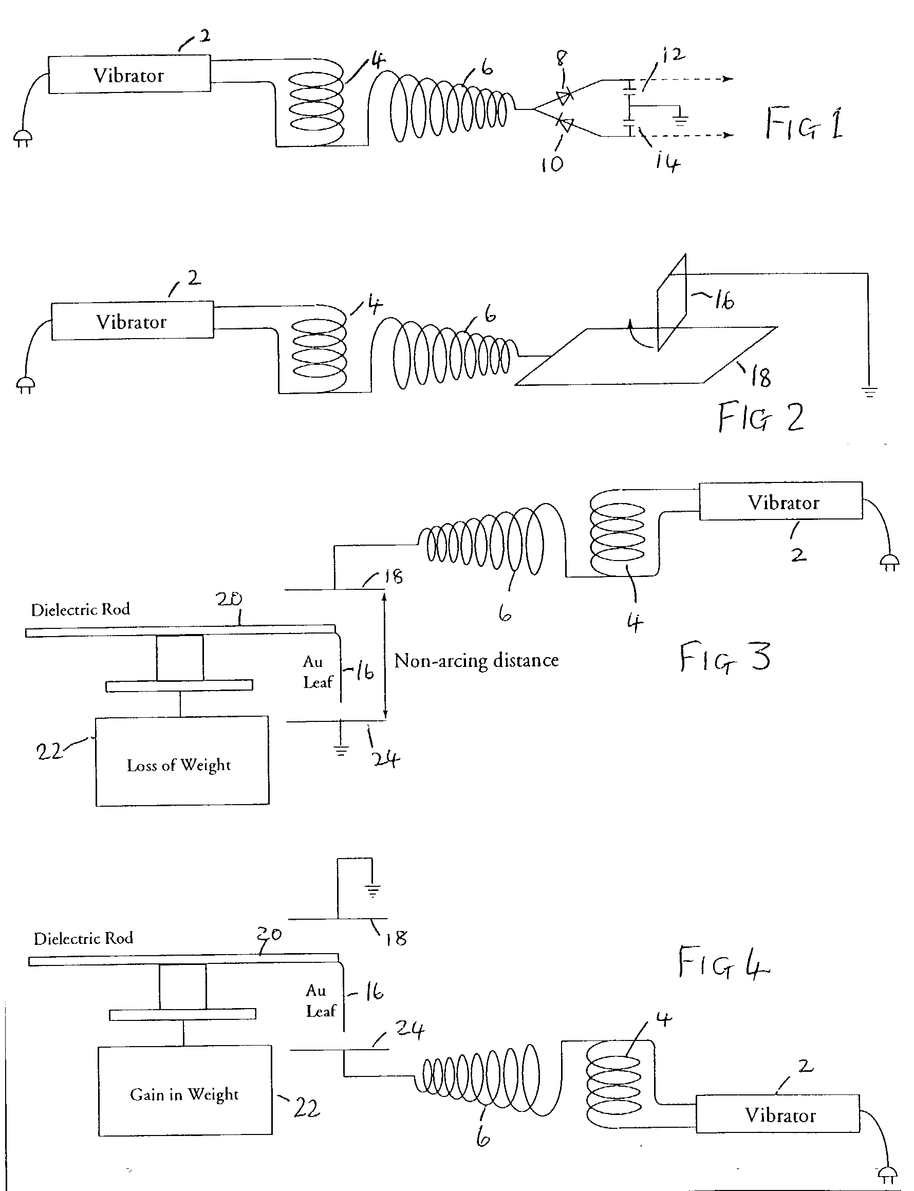
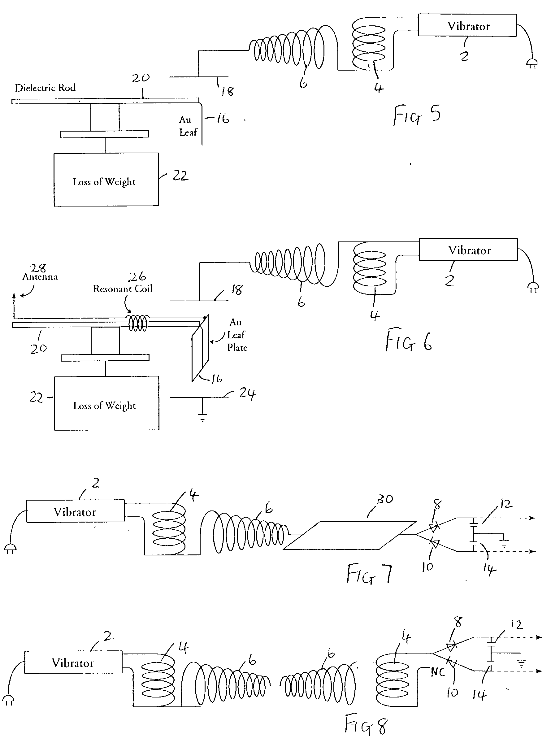
[0045] Based upon observations of weight loss in metallic matter as induced by exposure to high frequency alternating electric fields, we developed an experimental method to optimize this-weight loss, and from this a device that treats the forces causing weight loss as manifestations of intrinsic potential energy ΔU (or true “latent heat”) of the molecules of matter, and converts both “true latent heat” energy present in the neighbourhood of a receiver, and “sensible” heat induced within that receiver, into electric energy that can be employed to drive a motor, flywheel or charge battery supplies.

[0046] It is commonly believed that the output of the Tesla coil is ionizing electromagnetic radiation. We have demonstrated that it is not; i.e. that it is neither electromagnetic radiation, nor ionizing electromagnetic radiation. The output of an air cored, sequentially-wound secondary, consists exclusively of electric energy: upon contact with the coil, a massbound AC current can be ext...


PUM


Abstract

This invention relates to apparatus for the conversion of massfree energy into electrical or kinetic energy, which uses in its preferred form a transmitter and a receiver both incorporating Tesla coils, the distal ends of whose secondary windings are co-resonant and connected to plates of a chamber, preferably evacuated or filled with water, such that energy radiated by the transmitter may be picked up by the receiver, the receiver preferably further including a pulsed plasma reactor driven by the receiver coil and a split phase motor driven by the reactor. Preferably the reactor operates in pulsed abnormal gas discharge mode, and the motor is an inertially damped drag motor. The invention also extends to apparatus in which an otherwise driven plasma reactor operating in pulsed abnormal gas discharge mode in turn used to drive an inertially damped drag motor.,

Description

[0001] This is a continuation of application Ser. No. 09 / 907,823, filed Jul. 19, 2001.FIELD OF THE INVENTION [0002] This invention relates to systems for the conversion of energy, inter alia in the form of what we will refer to for convenience as Tesla waves (see below), to conventional electrical energy. BACKGROUND OF THE INVENTION [0003] Energy converters that are fed by local or environmental energy are usually explained by taking recourse to the notion that they convert zero point electromagnetic radiation (ZPE) to electric energy. The ZPE theories have gained a life of their own, as T. Kuhn has pointed out (in his “Black Body Theory and the Quantum”), after emerging from Planck's second theory, specifically from the term ½ hυ in the new formula for oscillator energy. In 1913, Einstein and Stern suggested that motional frequencies contributing to specific heat fell into two categories—those that were independent of temperature and those that were not (e.g. rotational energy), le...

Claims


Application Information

Patent Timeline
Patent Type & Authority Applications(United States)
IPC IPC(8): H02K33/00
CPCH02N11/002H02P31/00
Inventor CORREA, PAULO N.CORREA, ALEXANDRA N.
Owner CORREA PAULO N
Learn More