Eureka AIR delivers breakthrough ideas for toughest innovation challenges, trusted by R&D personnel around the world.

Thermal chirp compensation systems for a chirp managed directly modulated laser (CML(TM)) data Link

a direct modulated laser and compensation system technology, applied in the field of signal transmission, can solve the problems of thermal chirp, general undesirable thermal chirp, and distortion of optical output from desired waveform, and achieve the effect of reducing the effect of thermal chirp

Active Publication Date: 2006-04-13
II VI DELAWARE INC
View PDF82 Cites 28 Cited by
  • Summary
  • Abstract
  • Description
  • Claims
  • Application Information

AI Technical Summary

Benefits of technology

[0021] In the direct thermal compensation technique, a feed-forward type circuit is used to keep the temperature of the active region constant, independent of the mark density of the modulating bit sequence. The correction current is supplied to a heater, which is integrated with the laser chip and functions to change the chip temperature. The feed-forward correction signal is generated from the digital data modulating the laser. The direct thermal approach has the advantage that changes in laser temperature result in a pure frequency modulation without affecting output amplitude.
[0033] an electronic circuit adapted to modify the electronic digital data signal so as to additionally modulate the frequency modulated optical signal whereby to reduce the variations in the amplitude of the 1 and 0 logic levels in the amplitude modulated optical signal.
[0038] In another form of the invention, there is provided a semiconductor laser with two active regions thermally coupled to one another so that when the two active regions are electrically driven with modulation currents of opposite signs, heating in one region is counteracted by cooling in the other, so as to keep the two active regions of the semiconductor laser at a substantially constant temperature in order to reduce the effects of thermal chirp.

Problems solved by technology

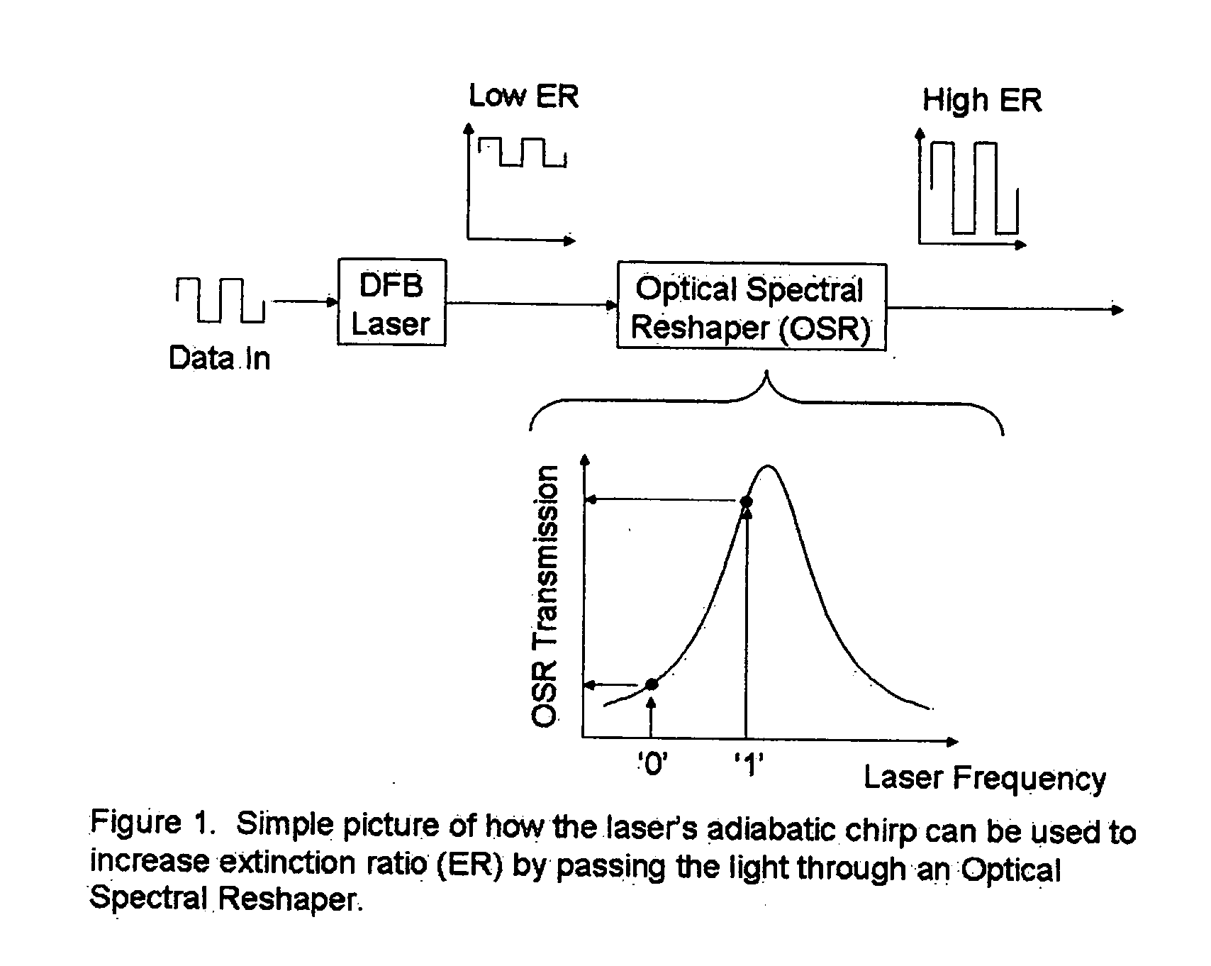
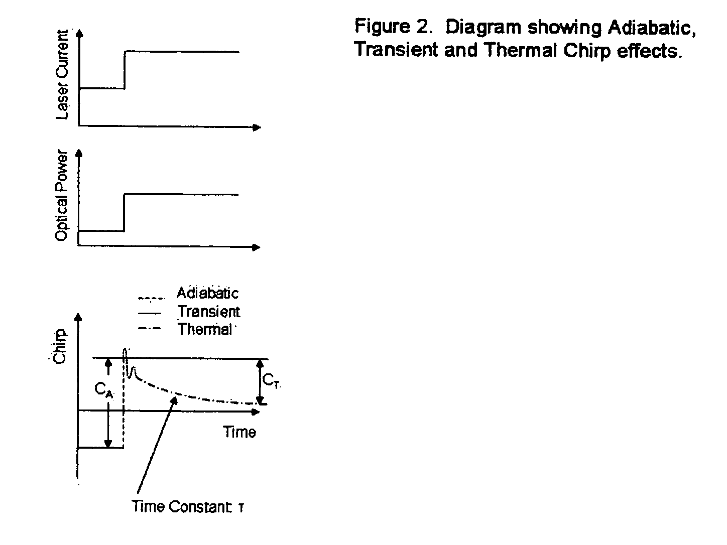
However, as shown below, a laser has other types of chirp which may cause distortions of the optical output from the desired waveform.
Thermal chirp is generally undesirable.
Hence, thermal chirp is generally undesirable in these systems.
This frequency wander can also cause another deleterious effect in data links with long lengths of optical fiber.

Method used


Image

  • Thermal chirp compensation systems for a chirp managed directly modulated laser (CML(TM)) data Link
  • Thermal chirp compensation systems for a chirp managed directly modulated laser (CML(TM)) data Link
  • Thermal chirp compensation systems for a chirp managed directly modulated laser (CML(TM)) data Link

Examples


Embodiment Construction

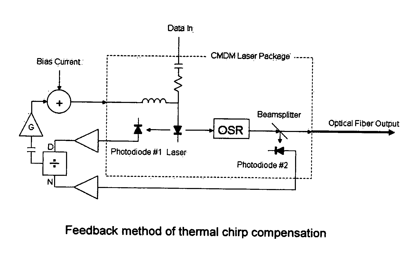
[0062] Thermal Chirp Compensation By The Feed-Forward Technique

[0063] The feed-forward approach of thermal chirp compensation is essentially an electronic equalization technique. Alexander et al. (S. B. Alexander, D. Welford, D. vL. Marquis, “Passive Equalization of Semiconductor Diode Laser Frequency Modulation,” J. Lightwave Technology, vol. 7, no. 1, pp 11-23, January 1989) described an electronic equalization system for purely frequency-modulated lasers. Their technique was meant for free-space communications applications which do not suffer from dispersion. This prior art was only concerned with correcting the frequency modulation of the laser.

[0064] The present invention, on the other hand, is tailored for the CML™ laser transmitter, for which the combination of AM and FM modulation need to be corrected. The method disclosed in the present invention can be adapted to equalize either the FM or AM output of the CML™. This is an important aspect for fiber-optic transmission whe...


PUM


Abstract

A fiber optic communication system for receiving an electronic digital data signal and transmitting the same, comprising an optical signal source adapted to receive the digital data signal and to produce a frequency modulated optical signal from a directly modulated semiconductor laser; an optical spectrum reshaper adapted to convert the frequency modulated optical signal into an amplitude modulated optical signal; and compensation apparatus for compensating for the adverse effects of the thermal chirp normally induced in the frequency modulated optical signal by modulating the semiconductor laser with the electronic digital data signal.

Description

REFERENCE TO PENDING PRIOR PATENT APPLICATIONS [0001] This patent application: [0002] (i) is a continuation-in-part of pending prior U.S. patent application Ser. No. 10 / 289,944, filed Nov. 6, 2002 by Daniel Mahgerefteh et al. for POWER SOURCE FOR A DISPERSION COMPENSATION FIBER OPTIC SYSTEM (Attorney's Docket No. TAYE-59474-00006); [0003] (ii) is a continuation-in-part of pending prior U.S. patent application Ser. No. 10 / 308,522, filed Dec. 3, 2002 by Daniel Mahgerefteh et al. for HIGH-SPEED TRANSMISSION SYSTEM COMPRISING A COUPLED MULTI-CAVITY OPTICAL DISCRIMINATOR (Attorney's Docket No. TAYE-59474-00007); [0004] (iii) is a continuation-in-part of pending prior U.S. patent application Ser. No. 10 / 680,607, filed Oct. 6, 2003 by Daniel Mahgerefteh et al. for FLAT DISPERSION FREQUENCY DISCRIMINATION (FDFD) (Attorney's Docket No. TAYE-59474-00009); [0005] (iv) is a continuation-in-part of pending prior U.S. patent application Ser. No. 11 / 068,032, filed Feb. 28, 2005 by Daniel Mahgereft...

Claims


Application Information

Patent Timeline
Patent Type & Authority Applications(United States)
IPC IPC(8): H04B10/04
CPCH01S5/024H01S5/042H01S5/06832H01S5/06837H04B10/504H04B10/58
Inventor JOHNSON, BARTMAHGEREFTEH, DANIELMCCALLION, KEVINPIEDE, DAVIDTAYEBATI, PARVIZ
Owner II VI DELAWARE INC
Why Eureka
Eureka Blog
Learn More