
Laser pumping unit and high power laser device tunnel junction including the same

a laser device and laser pumping technology, applied in the direction of laser details, excitation process/apparatus, optical resonator shape and construction, etc., can solve the problem that the electric pumping method in the vecsel cannot solve the problem of the vcsel, the current concentration at the edges of the aperture becomes serious, and it is difficult to produce single traverse mode oscillation

Active Publication Date: 2006-04-13
SAMSUNG ELECTRONICS CO LTD
View PDF9 Cites 12 Cited by
  • Summary
  • Abstract
  • Description
  • Claims
  • Application Information

AI Technical Summary

Benefits of technology

[0014] Embodiments of the present invention provide a laser pumping unit and a high power vertical external cavity surface emitting laser (VECSEL) including the same. The laser pumping unit does not have a loss due to free carrier absorption and may be easily manufactured by realizing current diffusion in a traverse direction using a simple structure.

Problems solved by technology

However, the electric pumping method in the VECSEL cannot solve the problem of the VCSEL.
Accordingly, a problem of current concentrating at the edges of the aperture becomes serious, and it becomes difficult to produce single traverse mode oscillation.
However, the laser 30 has problems.
More specifically, such a problem may be serious because the substrate 34 has a large thickness.
As a result, the efficiency of the laser device 30 of FIG. 3 is deteriorated.

Method used


Image

  • Laser pumping unit and high power laser device tunnel junction including the same
  • Laser pumping unit and high power laser device tunnel junction including the same
  • Laser pumping unit and high power laser device tunnel junction including the same

Examples


first embodiment

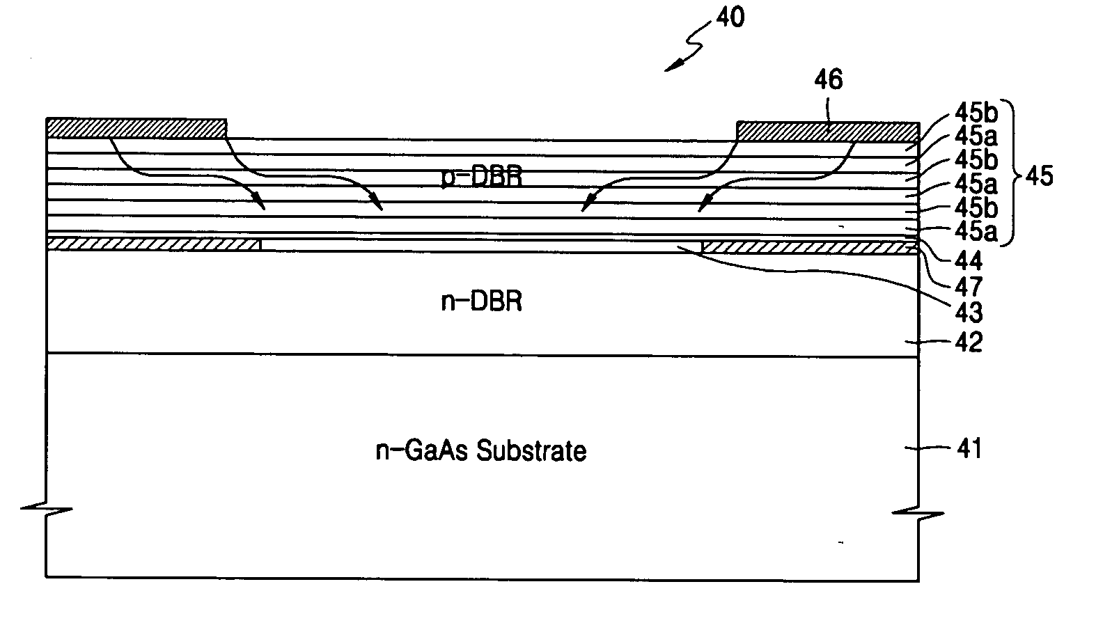
[0033]FIG. 4 is a sectional view of a laser pumping unit 40 having a tunnel junction layer according to the present invention. Referring to FIG. 4, the laser pumping unit 40 may include an n-GaAs substrate 41, a lower distributed brag reflector (DBR) layer 42, an active layer 43, a tunnel junction layer 44, and an upper DBR layer 45. In addition, a metal contact 46 for supplying current to the active layer 43 may be formed on the DBR layer 45. An oxide layer 47 may be formed at the edge of the active layer 43 to restrict the size of an aperture that acts as a current injection area. An ion injection layer may be used instead of the oxide layer 47.

[0034] The tunnel junction layer 44 may increase resistance in a vertical direction to facilitate the distribution of current in a traverse direction. In a conventional laser device, the current injected through a metal contact located at the edge of an upper DBR layer is not sufficiently transferred to the center of an active layer but is ...

second embodiment

[0041]FIG. 7 is a sectional view of a laser pumping unit according to the present invention. Referring to FIG. 7, a tunnel junction layer 44 partially covers an active layer 43. In addition, an upper DBR layer 45 may be formed on the tunnel junction layer 44 and the active layer 43. Accordingly, the tunnel junction layer 44 may be buried by the upper DBR layer 45. As a result, a portion of the upper DBR layer 45 formed on the tunnel junction layer 44 may be a ridge higher than the other portion of the upper DBR layer 45. A light generated in the active layer 43 travels vertically within the ridge portion. Thus, the ridge portion of the upper DBR layer 45 may operate as an aperture.

[0042] In addition, when a doping concentration of a high refractive index layer 45b is greater than a doping concentration of a low refractive index layer 45a in the upper DBR layer 45, an energy band shown in FIG. 8 may be formed. As a result, current supplied from a contact layer 46 may flow within the ...


PUM


Abstract

Embodiments include a laser pumping unit and a high power vertical external cavity surface emitting laser (VECSEL) device including the same. The laser pumping unit easily diffuses current in a traverse direction by using a tunnel junction. The laser pumping unit may include a substrate, a lower distributed brag reflector (DBR) layer formed on the substrate, an active layer with a quantum well structure formed on the lower DBR layer to generate a light having a predetermined wavelength, a tunnel junction layer formed on the active layer to increase resistance in a vertical direction, and an upper DBR layer formed on the tunnel junction layer.

Description

BACKGROUND OF THE DISCLOSURE [0001] This application claims the priority of Korean Patent Application No. 10-2004-0081059, filed on Oct. 11, 2004, in the Korean Intellectual Property Office, the disclosure of which is incorporated herein in its entirety by reference. [0002] 1. Field of the Disclosure [0003] The present invention relates to a laser pumping unit having a tunnel junction and a high power laser device including the same, and more particularly, to a laser pumping unit and a high power vertical external cavity surface emitting laser (VECSEL) of easily diffusing current in a traverse direction by using the tunnel junction including the same. [0004] 2. Description of the Related Art [0005]FIG. 1 is a sectional view of a conventional vertical cavity surface emitting laser (VCSEL) 10, which emits a laser beam in a perpendicular direction to a substrate. Referring to FIG. 1, the conventional VCSEL 10 is formed by sequentially stacking a substrate 11 formed of n-GaAs, a lower d...

Claims


Application Information

Patent Timeline
IPC IPC(8): H01S5/00
CPCH01S3/109H01S5/141H01S5/18308H01S5/18311H01S5/18327H01S5/18388H01S5/3095H01S2301/18H01S3/09H01S5/183
Inventor KIM, TAEK
Owner SAMSUNG ELECTRONICS CO LTD
Learn More