Image reading device and method of scaling up or down image to be read

Inactive Publication Date: 2006-04-13
NEC CORP
View PDF2 Cites 11 Cited by
  • Summary
  • Abstract
  • Description
  • Claims
  • Application Information

AI Technical Summary

Benefits of technology

[0010] In view of the above, it is an object of the present invention to provide an image reading device in which an image with satisfactory definition can be obtained, as required, without causing an increase in the number of reading pixels and with reduction in costs, and a method of scaling up or down an image to be read, that can be used in the image reading device.
[0026] wherein the image scaling unit changes an angle or a position of at least one specified mirror element of the mirror assembly so that light having arrived from the original document is guided into the lens with a decreased number of times of reflection by the mirror assembly occurring during a time period before light having arrived from the original document reaches the lens and shortens a length of an optical path between the original document and the lens so that the image of the original document to be formed on the image pickup plane of the image sensor is enlarged.
[0028] Another preferable mode is one wherein the image scaling unit moves at least one specified mirror element of the mirror assembly out of an optical path and to allow light having arrived from the original document to strike at least one other specified mirror element of the mirror assembly so that a length of the optical path between the original document and the lens is shortened.
[0038] wherein, in the image enlarging or reducing step, an angle or a position of at least one specified mirror element of the mirror assembly is changed so that light having arrived from the original document is guided into the lens with a decreased number of times of reflection by the mirror assembly occurring during a time period before light having arrived from the original document reaches the lens and a length of an optical path between the original document and the lens is shortened so that the image of the original document to be formed on the image pickup plane of the image sensor is enlarged.
[0043] With the above configuration, the image enlarging or reducing means employed in the image reading device changes a length of an optical path between the original document and the lens to cause a change in a scaling factor of the image to be formed on the image sensor, when positions of specified mirror elements making up a mirror assembly are changed to shorten a length of the optical path so that light having reached from the original document is allowed to enter the lens with a decreased number of times of reflection of the light occurring before the light reaches the lens in the mirror assembly and, as a result, the image to be formed on the image sensor is enlarged, which enables the image with satisfactory definition to be obtained, as required, without causing an increase in the number of pixels and with reduction in costs. Moreover, further reduction in costs can be realized simply by adding a driving means serving as an image enlarging and reducing means used to change positions of specified mirror elements to an existing conventional image reading device employing the reduction-type optical means.

Problems solved by technology

However, in either of the above methods, to obtain image data with high definition, an increase in the number of reading pixels per unit length is required.
As a result, a problem arises that the increase in the number of pixels causes an area of one pixel to become smaller and an output to decrease and a signal-to-noise (S / N) ratio to become lower.
Moreover, there is another problem that, due to the increase in the number of pixels, amounts of data for an entire image and of calculation required for image processing become enormous and required storage capacity increases and, as a result, much time is required for the processing, causing costs to become high.
Additionally, another problem arises that, due to the increase in the number of pixels, introduction of a high-priced contact-type image sensor or CCD is required and, in the case of the reduction-type optical method, use of a lens with high resolution is required, causing costs to increase and dimensions to become larger and thus, miniaturization is made difficult.
However, the above conventional technology has a problem in that, when optical systems are to be moved, since mirrors or a like are moved forward or backward on an optical axis, a scaling factor of an image can be changed only in a comparatively narrow range and, as a result, definition and / or quality of an image cannot be improved satisfactorily.

Method used


Image

  • Image reading device and method of scaling up or down image to be read
  • Image reading device and method of scaling up or down image to be read
  • Image reading device and method of scaling up or down image to be read

Examples


first embodiment

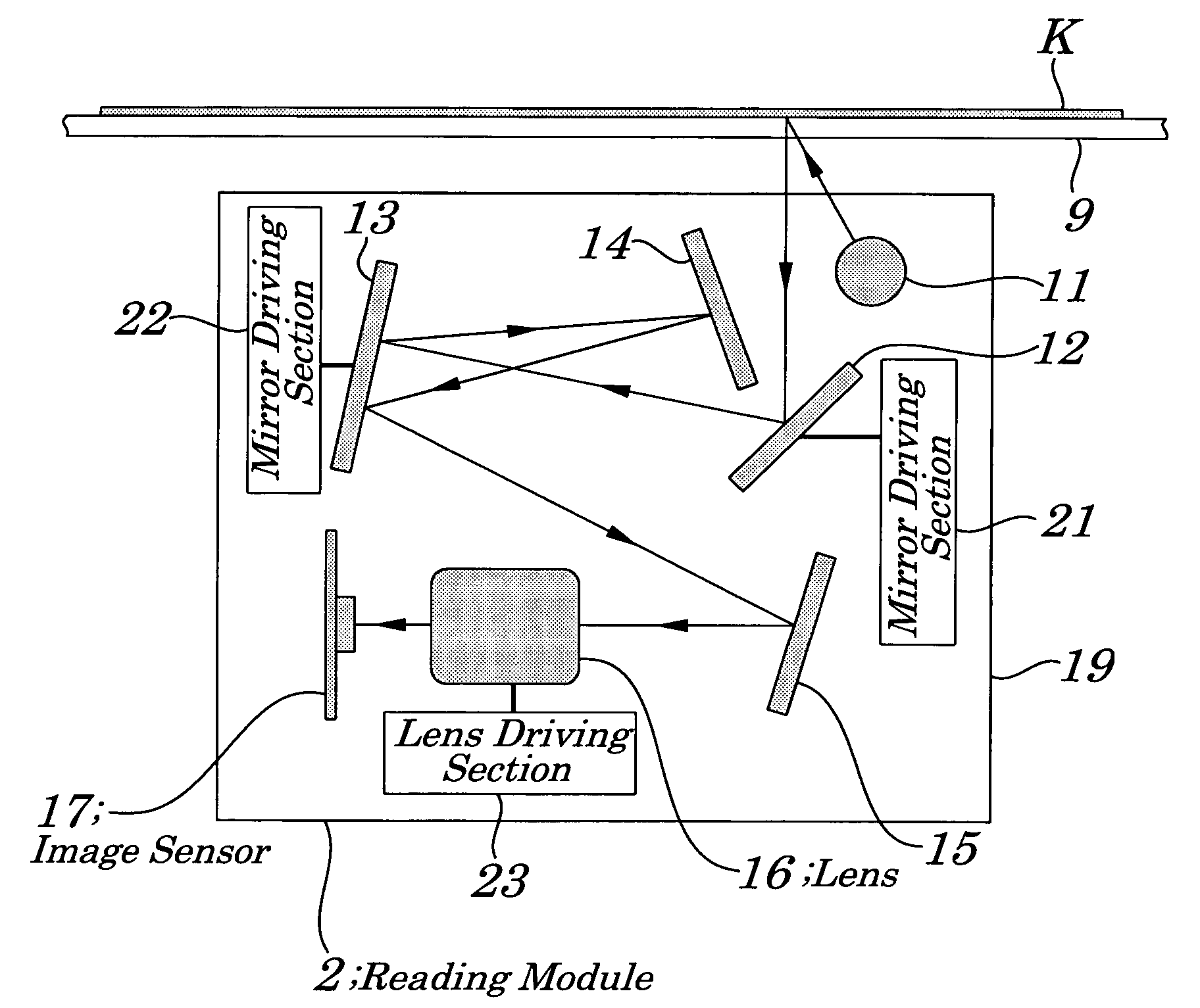
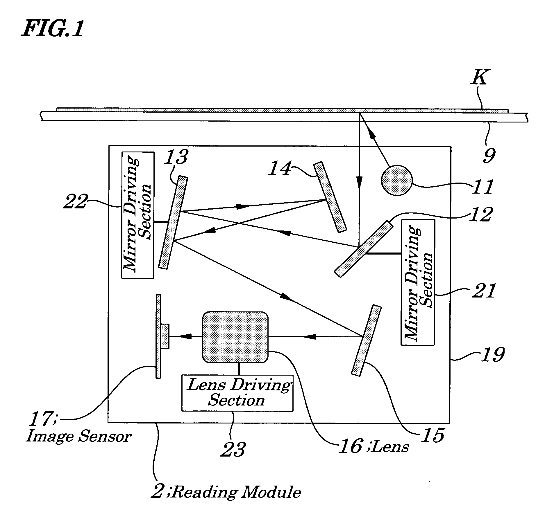
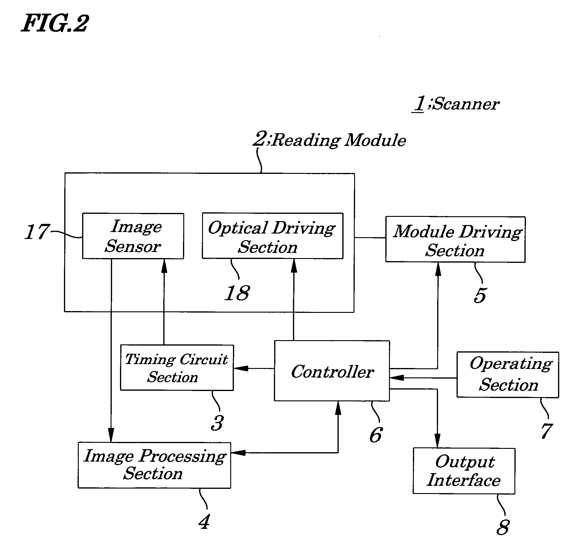
[0055]FIG. 1 is a diagram schematically showing configurations of a reading module 2 of a scanner 1 according to a first embodiment of the present invention. FIG. 2 is a block diagram showing configurations of the scanner 1 of FIG. 1. FIG. 3 is a schematic diagram for explaining configurations of the scanner 1 of FIG. 1. FIG. 4 is a block diagram showing configurations of an optical driving section 18 of the reading module of FIG. 1. FIG. 5 is a schematic diagram for explaining configurations of a mirror driving section 21 making up the optical driving section 18 of FIG. 4. FIG. 6 is a block diagram showing configurations of a controller 6 of the scanner 1 of FIG. 1. FIG. 7 is a schematic diagram for explaining operations of the reading module 2 of FIG. 1.

[0056] The scanner 1, as shown in FIG. 1, performs operations of reading of an original document along a main scanning direction M (FIG. 3), which includes the reading module 2 (FIG. 2) being movable along a sub-scanning direction...

second embodiment

[0075]FIG. 8 is a diagram schematically showing configurations of a reading module 2A of a scanner according to a second embodiment of the present invention. FIG. 9 is a schematic diagram for explaining operations of the scanner of the second embodiment.

[0076] Configurations of the reading module 2A of the second embodiment differ from those of the reading module 2 of the first embodiment in that a first mirror 12 is moved out of an optical path and a fourth mirror 15 is made to be driven. Configurations other than described here are approximately the same as those of the first embodiment and their descriptions are omitted or simplified accordingly, by using a same numeral in FIG. 8, concerning a same component as that shown in FIG. 5.

[0077] A reading module 2A of the scanner of the second embodiment, as shown in FIG. 8, includes a light source 11, a first mirror 12, second mirror 13, third mirror 14, and fourth mirror 15 all being arranged on an optical path to reflect light havi...


PUM


Abstract

An image reading device is provided which is capable of obtaining an image with satisfactory definition without causing an increase in the number of reading pixels and with reduction in costs. Mirror driving sections change a length of an optical path between an original document and a lens to change a scaling factor of an image to be formed on an image sensor. When high-density reading of a small-sized original document rendering a narrow reading range is required, specified mirrors are rotated to prevent light from travelling through a mirror so as to guide the light into a lens with the decreased number of times of reflection by mirrors occurring during a time period before the light reaches a lens and so that a length of an optical path is shortened, which enables an image, to be formed on an image sensor, to be enlarged.

Description

BACKGROUND OF THE INVENTION [0001] 1. Field of the Invention [0002] The present invention relates to an image reading device and a method of scaling up or down an image to be read, and more particularly to the image reading device in which a module having a light source, image sensor, mirrors, and lens to form a reduced optical image of an original document on the image sensor in its cabinet is configured to scan the original document being fixed on, for example, a flat-shaped contact glass to read an image of the original document and the method of scaling up or down the image to be read, to be used in the image reading device, that is, a method for enlarging or reducing image of the original document. [0003] The present application claims priority of Japanese Patent Application No. 2004-299460 filed on Oct. 13, 2004, which is hereby incorporated by reference. [0004] 2. Description of the Related Art [0005] Conventionally, a scanner serving as an image reading device making up an i...

Claims


Application Information

Patent Timeline
IPC IPC(8): H04N1/04
CPCH04N1/0402H04N1/0411H04N1/0423H04N1/0432H04N1/0455H04N1/1017H04N1/193
Inventor ITOU, AKIHIDE
Owner NEC CORP
Why Eureka
Try Eureka