Sensor device and wiper controller
a technology of sensor device and wiper controller, which is applied in the direction of vehicle cleaning, instruments, dynamo-electric converter control, etc., can solve the problems of increased production cost, increased cost, and change in the amount of light received by the light reception device, and achieve high cost-performance, high space efficiency, and high accuracy in raindrop detection.
- Summary
- Abstract
- Description
- Claims
- Application Information
AI Technical Summary
Benefits of technology
Problems solved by technology
Method used
Image
Examples
first embodiment
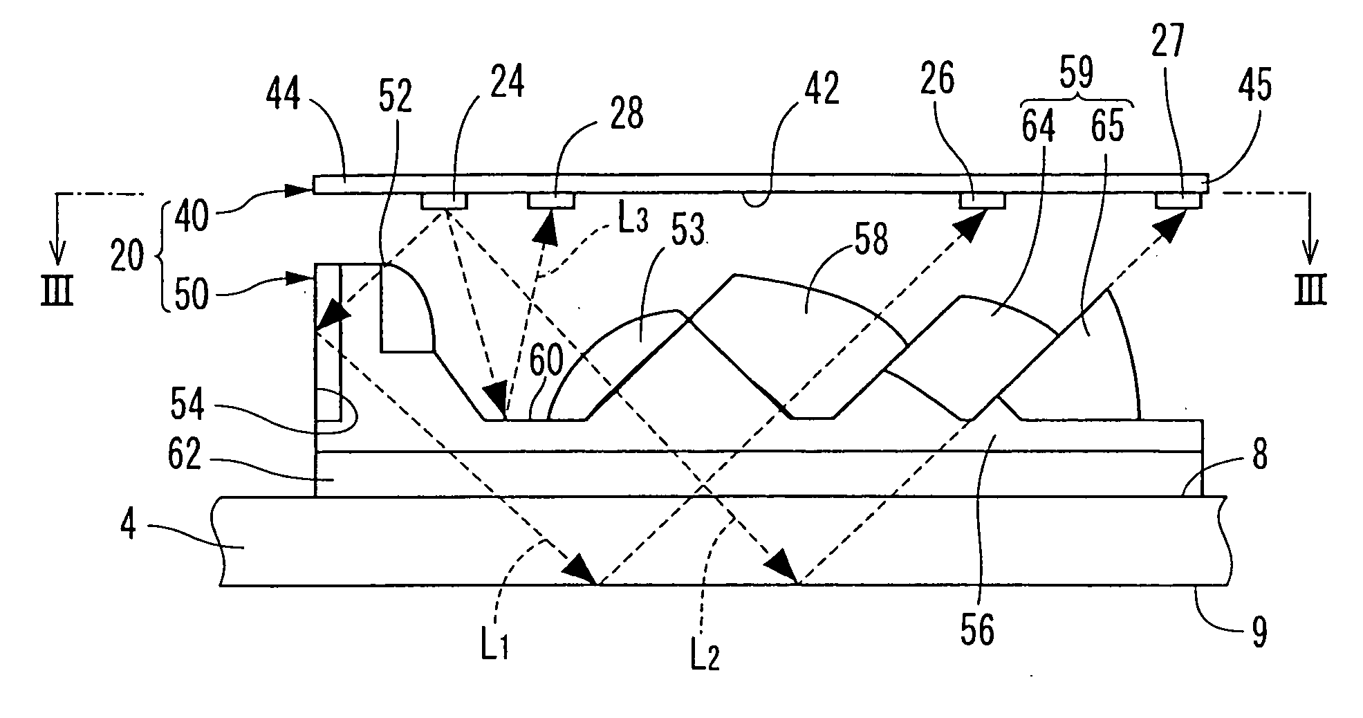
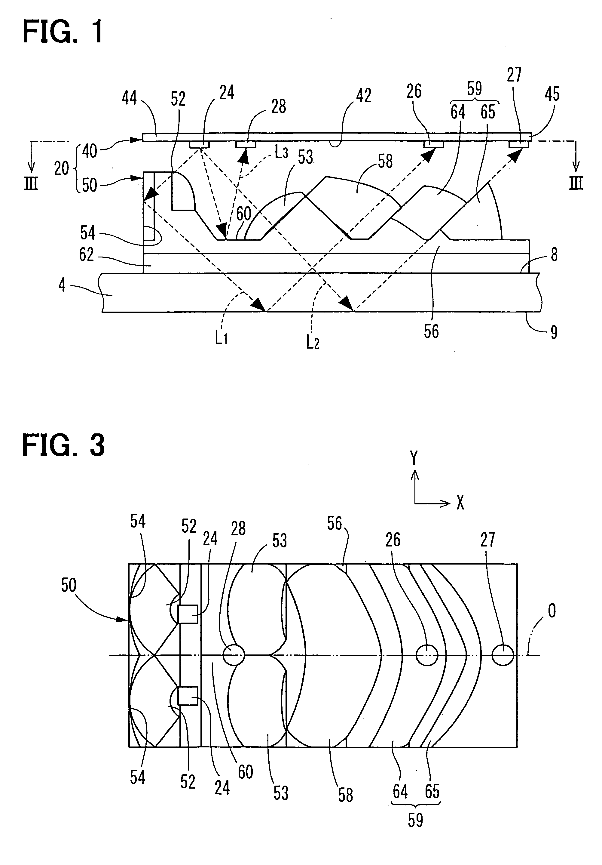
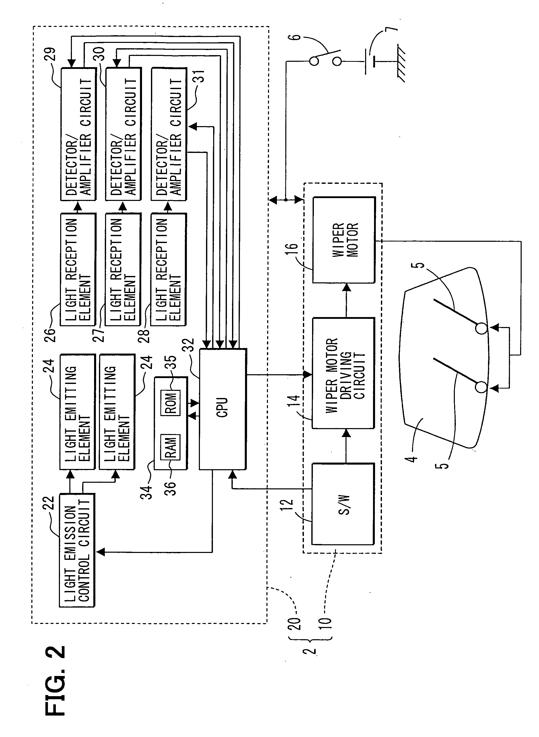
[0045]FIG. 2 shows a block diagram of a wiper controller in the first embodiment of the present invention. The wiper controller 2 controls wipers 5 used in a vehicle for wiping raindrops on a windshield 4.
[0046] The wiper controller 2 includes a wiper driving device 10 and a raindrop detection device 20. Electric power supply is provided from a battery 7 to the wiper driving device 10 and the raindrop detection device 20 through an ignition switch 6.
[0047] The wiper driving device 10 includes a wiper switch 12, a wiper motor driving circuit 14, and a wiper motor 16. The wiper switch 12 is disposed at a position that is close to a driver's seat in the vehicle. The wiper switch 12 has a plurality of control positions of wiping operation such as “auto,”“low,”“middle,”“high,”“stop” and the like. The wiper switch 12 outputs a control position signal that indicates a control position of the switch 12 to the wiper motor driving circuit 14 and a CPU 32 in the raindrop detection device 20....
second embodiment
[0085] In the present embodiment, the wiper controller processes the regular rain detection in the same way as the initial rain detection as described in the first embodiment. That is, steps S31 to S35 in the flowchart in FIG. 9 are the same as steps S11 to S15 in the flowchart in FIG. 6 in the first embodiment. In this manner, the control process of the wiper controller is simplified without compromising the accuracy of detection.
third embodiment
[0086] The regular rain detection of the wiper control process in a third embodiment of the present invention is described with reference to a flowchart in FIG. 10.
[0087] The regular rain detection starts with step S41, which is the same process as step S11 in the initial rain detection.
[0088] In step S42, three fail-safe criteria are examined. That is, the process proceeds to step S43 if at least one of the three criteria is met. In this case, the process is determined as a normal condition. The process proceeds to step S47 if all of the three criteria are met. The process proceeds to step S47 for handling an abnormal condition based on the examination of the three criteria.
[0089] The three criteria for fail-safe are as follows: [0090] (1) Each of the amounts R1, R2 of the light received by the first and second light reception elements stored in the RAM 36 in step S41 is not 0; [0091] (2) The amount R3 of the light received by the third light reception element is 0; and [0092] (...
PUM
 Abstract
Description
Claims
Application Information
 - R&D
- Intellectual Property
- Life Sciences
- Materials
- Tech Scout
- Unparalleled Data Quality
- Higher Quality Content
- 60% Fewer Hallucinations
Browse by: Latest US Patents, China's latest patents, Technical Efficacy Thesaurus, Application Domain, Technology Topic, Popular Technical Reports.
© 2025 PatSnap. All rights reserved.Legal|Privacy policy|Modern Slavery Act Transparency Statement|Sitemap|About US| Contact US: help@patsnap.com


