
Timing circuit for data packet receiver

a timing circuit and data packet technology, applied in the direction of digital transmission, pulse automatic control, angle demodulation by phase difference detection, etc., can solve the problems of frequency drift, frequency drift, frequency drift, etc., and achieve low timing jitter and increase overhead

Inactive Publication Date: 2006-03-30
LUCENT TECH INC
View PDF9 Cites 14 Cited by
  • Summary
  • Abstract
  • Description
  • Claims
  • Application Information

AI Technical Summary

Benefits of technology

[0018] The present invention involves the recognition that acquiring the frequency of the data rate by monitoring the data received is not necessary for data packets, particularly burst data packet transmissions. Not only is it not necessary, but it is also potentially detrimental as described above with respect to frequency drift during idle periods. Specifically, the feedback to the frequency oscillator employed in conventional phase-locked loop (PPL) circuitry results in frequency drifts during idle times, necessitating longer re-sync times and, thus, increasing overhead.
[0019] The present invention avoids this problem by providing a timing circuit architecture for a receiver which does not acquire the data rate frequency by monitoring the incoming data, but rather establishes a clock signal using a local reference clock which is fixed and independent of the data packets. The reference clock is preferably the same reference clock used by the transmitter in generating the data so the frequency of the data rate is established in the same fashion at both the receiver and the transmitter. In other words, the receiver uses a high-precision PLL to generate a local clock at the required data rate frequency with low timing jitter and phase noise, similar to the transmitter.
[0021] By decoupling frequency and phase acquisition, the receiver of the present invention is well suited to handle long idle times in which no data are received. While standard PLLs suffer from frequency drifts during long idle times resulting in prolonged synchronization times or synchronization failures, the PLL-DLL receiver concept of the present invention eliminates frequency drifts during idle times so that the synchronization time of the receiver is solely determined by the loop bandwidth of the DLL and is therefore more predictable. Furthermore, since the same PLL for generating a high-frequency clock out of a low-frequency reference clock is used on the transmitter and receiver side, a burst-mode transceiver chip can be implemented with only one PLL that is shared for transmit and receive side. This may minimize power consumption, chip size and complexity.

Problems solved by technology

Not only is it not necessary, but it is also potentially detrimental as described above with respect to frequency drift during idle periods.
Specifically, the feedback to the frequency oscillator employed in conventional phase-locked loop (PPL) circuitry results in frequency drifts during idle times, necessitating longer re-sync times and, thus, increasing overhead.

Method used


Image

  • Timing circuit for data packet receiver
  • Timing circuit for data packet receiver
  • Timing circuit for data packet receiver

Examples


Embodiment Construction

[0029] The present invention provides a timing circuit architecture for transmission systems in which packets or bursts of data are transmitted at a known and fixed clock frequency. Referring to FIG. 1, a schematic of a preferred embodiment of a data packet receiver 1 of the present invention is show. The receiver 1 is suitable for receiving data packet transmissions having sporadic or burst data packets. Each data packet comprises data having a particular data frequency. The receiver 1 comprises (1) a clock generating circuit 2 for generating a clock signal which is derived from a fixed reference clock signal and not from received data packets; and (2) a phase shifter circuit 3 for synchronizing the phase of the clock signal to that of the received data packet transmissions by sampling the data packets. These two circuits are discussed below in greater detail.

[0030] The frequency generation circuit 2 functions to establish the frequency of the data rate without sampling the receiv...


PUM


Abstract

A timing circuit for a receiver adapted for receiving data packet transmissions, each packet having a particular data frequency, the timing circuit comprising: (a) a clock generating circuit for generating a clock signal derived from a local reference clock signal and not from received data packets; and (b) a phase shifter circuit for synchronizing the phase of the clock signal to that of the particular data frequency

Description

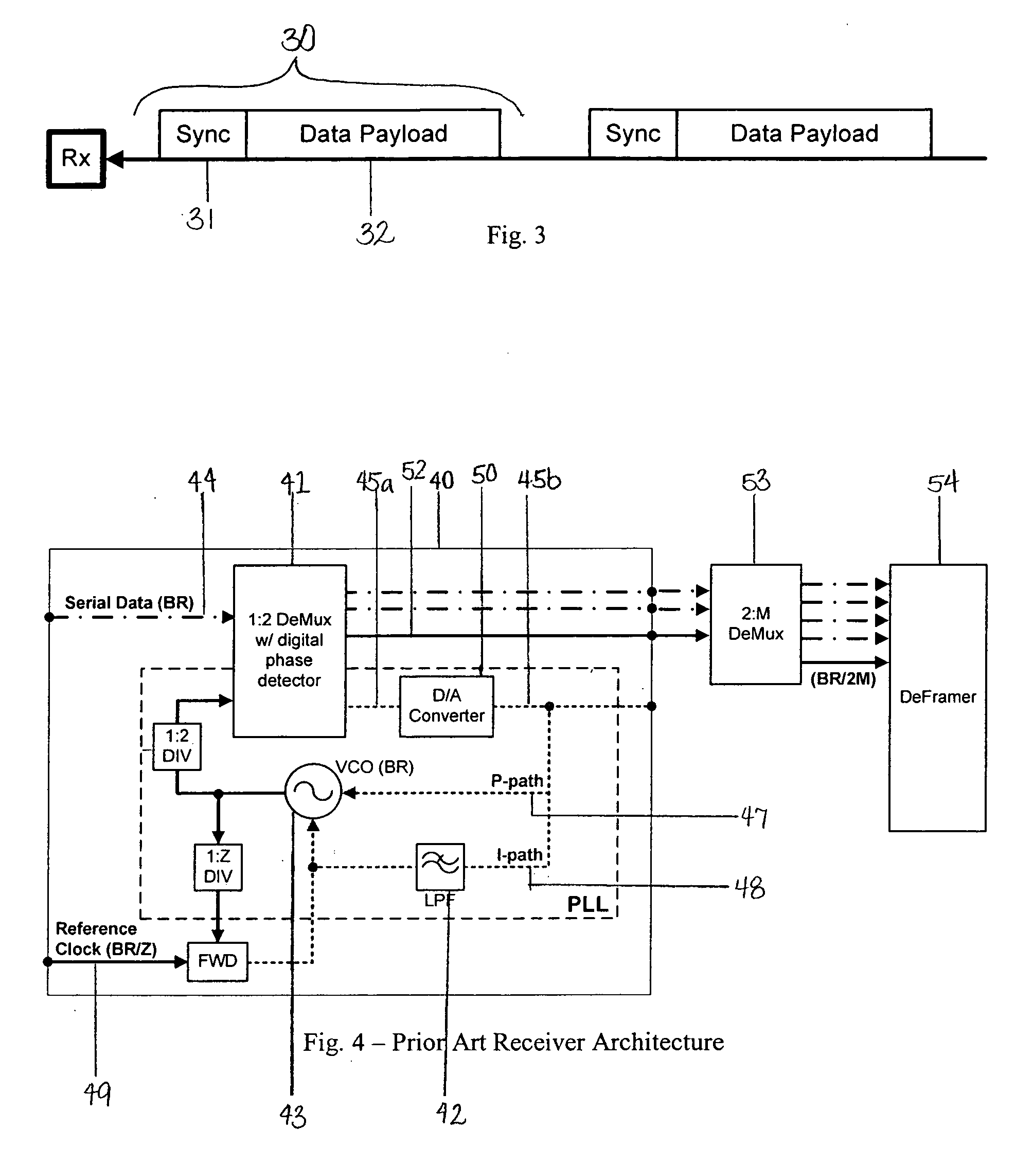
FIELD OF INVENTION [0001] The present invention relates generally to a timing circuit for a receiver, and, more specifically, to a timing circuit for a receiver especially adapted for receiving separated or bursts of data packets. BACKGROUND [0002] In the data communication field, applications have arisen recently requiring information to be transmitted as separated data packets or bursts of data packets, rather than as a continuous and synchronous stream of data. Examples of such applications include Ethernet, Passive Optical Networks (PONs) or packet routing and switching. These new applications present challenges over traditional continuous and synchronous transmissions as described below. [0003] By way of background, the various types of data transmission are illustrated in FIG. 2. Scheme (A) illustrates a conventional transmission of data between a transmitter and a receiver in a continuous and synchronous mode over dedicated point-to-point connections at a fixed clock frequenc...

Claims


Application Information

Patent Timeline
Patent Type & Authority Applications(United States)
IPC IPC(8): H03D3/24
CPCH03L7/0812H03L7/10H04L7/0037H03L7/07H04L7/02H03L7/1075
Inventor DUELK, MARCUS
Owner LUCENT TECH INC
Learn More