
Flexible and semi-permeable means of hydrogen delivery in storage and recovery systems

a technology of hydrogen delivery and storage system, which is applied in the direction of electrochemical generators, lighting and heating apparatus, packaging goods types, etc., can solve the problems of reducing the weight of the container, reducing the storage method, and requiring comparatively bulky storage containers

Inactive Publication Date: 2006-03-30
MPD TECH
View PDF8 Cites 16 Cited by
  • Summary
  • Abstract
  • Description
  • Claims
  • Application Information

AI Technical Summary

Benefits of technology

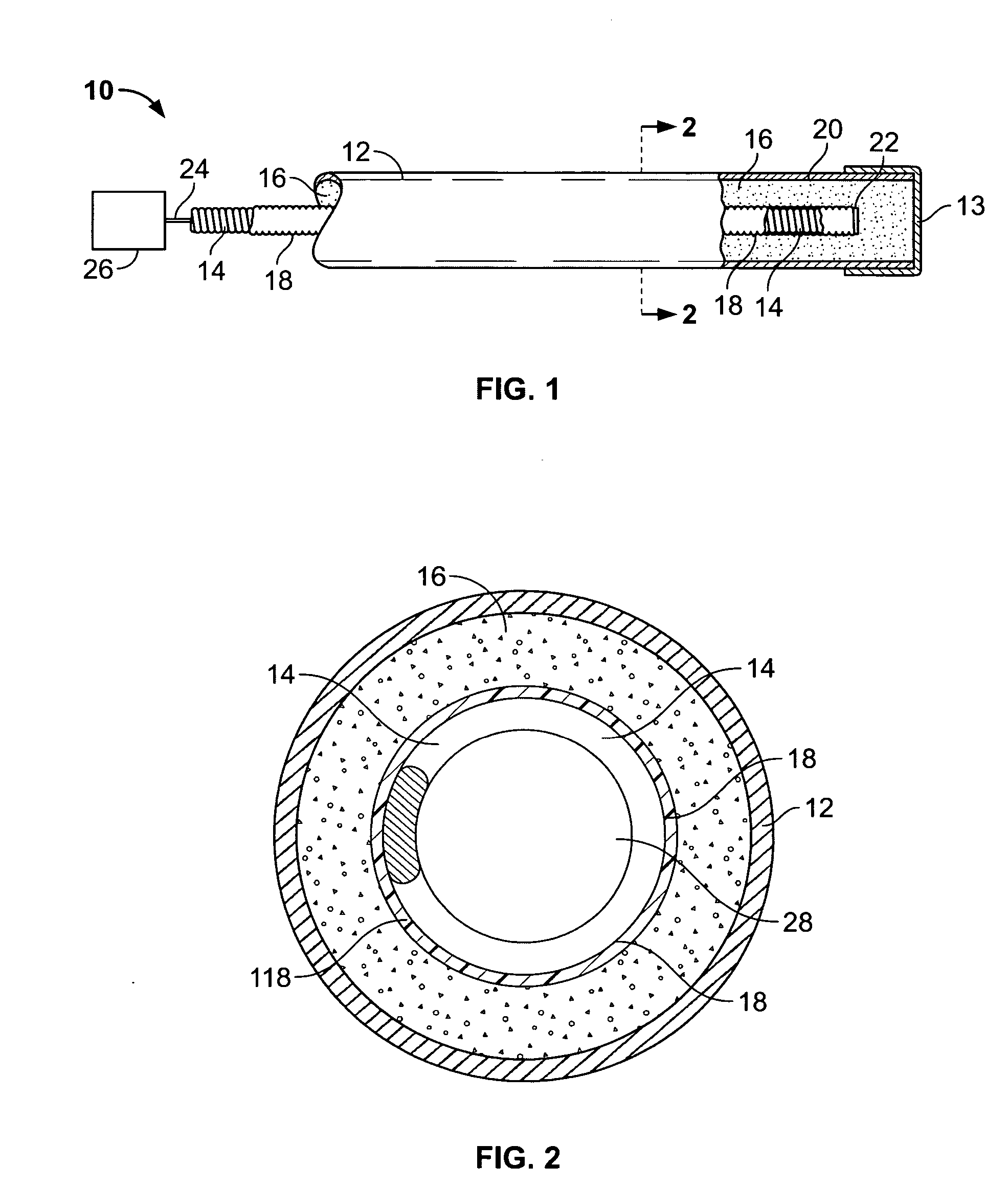
[0012] Accordingly, there is provided a hydrogen storage unit comprising an enclosed container defined by a container wall and having an opening for receiving and discharging gaseous hydrogen within the enclosed container, a flexible hydrogen dispersion assembly including an elongated central longitudinal conduit passage for evenly distributing hydrogen essentially throughout the enclosed container, the passage being defined by a tubular structural member being covered by an encasing film comprising an inert semi-permeable membrane, and metal hydride material packed within the enclosed container between the flexible hydrogen dispersion assembly and the container wall so as to essentially surround the hydrogen dispersion assembly. The tubular structural member may take a number of forms, such as a tube, and including a plurality of pre-stressed hollow springs, substantially filling up the space along the entire length of the tube, that are essentially longitudinally disposed within the tube. A bed of hydride material is packed around the tube, so as to fill the void between the tube and the inner wall of the container. One end of the tube may be sealed, and the other may be open to permit ingress and egress of hydrogen gas therethrough. Alternatively, a flexible conduit may be interspersed within selected ones of the longitudinal structural members, and hydride material may be packed within the springs, which provide for expansion protection.

Problems solved by technology

Both methods of storage require comparatively bulky storage containers that are often in need of maintenance.
In addition to their unwieldy size, such containers are inconvenient due to the high pressure required for gas storage in cylinders, which can contribute to the possibility of hydrogen gas leakage from the cylinders.
Although the weight of the metal hydride powder is a consideration, there may result a concomitant reduction in the weight of the container, since excessively large pressures will not be encountered, and thick container walls are not as significant.
One difficulty that has been investigated is high stress due to the compaction of the powder and expansion thereof during hydride formation.
These stress forces are directed against the walls of the storage container and may damage the container itself or the associated internal assemblies unless provision is made to accommodate the impact of the forces.
Such rupture may become dangerous since a fine, often pyrophoric powder may be expelled by pressurized, flammable hydrogen gas.
Small, experimental cylinders of the aforedescribed type have indeed been found to open and burst when subjected to repetitive charging-discharging cycles, because of repeated and progressively more invasive structural and compressive stresses.
Additionally, it is undesirable for containers to lose their integrity since any hydrogen stream expelled out of a hydride container may be subject to combustion with possibly catastrophic results.
While the solution to the problem of hydride powder compaction described in the above-described patents are normally adequate to control excessive bulging and deformity of the container by absorbing the stress of metal hydride particles expanding as hydrogen is absorbed therein, that solution has been found to lead to unintended and undesirable results when the hydride materials are subjected to numerous hydrogen absorption / desorption cycles.
This reduces flow efficiency, and if enough hydride material is injected into the conduit, blocks hydrogen flow, thereby defeating the purpose of the spring elements.

Method used


Image

  • Flexible and semi-permeable means of hydrogen delivery in storage and recovery systems
  • Flexible and semi-permeable means of hydrogen delivery in storage and recovery systems
  • Flexible and semi-permeable means of hydrogen delivery in storage and recovery systems

Examples


second embodiment

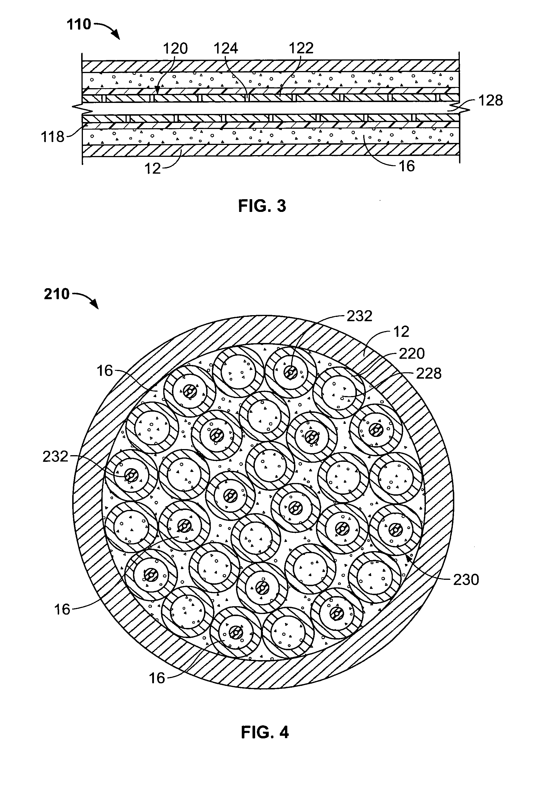
[0029] The conduit wall 122, being made of a sturdy material, provides a structural member that can withstand the expansion of hydride while maintaining its integrity and retaining the capability to transfer hydrogen gas through the passage 128 longitudinally. Simultaneously, the film 118 permits only hydrogen to penetrate into the hydride material 16. The remaining elements of the second embodiment may have structures similar to that shown in FIG. 1, and may have other modifications, for example, elements to accommodate hydride expansion, as described above.

third embodiment

[0030] In a third embodiment, a unit 210, shown in a transverse, cross-sectional view in FIG. 4, the spring 14 shown in FIG. 1 may be replaced by a plurality of sturdy, rigid tubular members 220, so as to provide added protection of the conduit material by a compartmentalization of the separate passageways provided for hydrogen dispersal. These members may be identical to the flexible springs in the prior art devices, but having a smaller diameter, that are permeable to gas through the coils of the sturdy, rigid tubular members 220.

[0031] Unlike the prior art devices of the aforementioned '114 patent, however, or the second embodiment illustrated in FIG. 3, the tubular members 220 do not have a surrounding sheath of material to retain the physical barrier to the transposition or shifting of the hydride material 16 contained within the outer wall 12 of the unit 210. Instead, each of the tubular members 220 has a central passage in the form of a central tubular space. This central tub...


PUM

PropertyMeasurementUnit
Thicknessaaaaaaaaaa
Forceaaaaaaaaaa
Flexibilityaaaaaaaaaa

Abstract

A container for use in hydrogen transfer includes structural tubular members and perforations for fluid communication with a central passage covered with a film that is selectively permeable to hydrogen, but not to other gases. The tubular member walls comprise a sturdy material to fix the hydride powder, preventing it from shifting within the container. The hydrogen flow, when being absorbed or desorbed by the metal hydride, will pass through the film both as it is absorbed in the hydride material and also after it is desorbed to pass into the central passage. Simultaneously, the tubular member material, acting as a flexible cover or support for the film, retains contaminant gases within the conduit passage, but permits hydrogen to flow therethrough. Alternatively, a flexible conduit may be interspersed within selected ones of the longitudinal structural members, and hydride material may be packed within the springs, which provide for expansion protection.

Description

BACKGROUND OF THE INVENTION [0001] 1. Field of the Invention [0002] This invention relates generally to an apparatus for transferring, storing and recovering hydrogen from a hydridable material and more particularly to such an apparatus used for transferring hydrogen under pressure while simultaneously removing any gaseous impurities from the hydrogen stream before the hydriding step. [0003] 2. Background Art [0004] Hydrogen in the combinant form of water has long been employed in many chemical processes. Recent advances have permitted use of elemental hydrogen in gaseous form in physical processes, such as in heat transfer and electrical energy storage. For example, the fuel cell industry, among others, is continually developing new applications for hydrogen, including fuel cells and heat transfer applications. As a result there is a growing need to store hydrogen safely and conveniently in such applications. [0005] Hydrogen has been stored conventionally as a gas in steel cylinder...

Claims


Application Information

Patent Timeline
IPC IPC(8): B65B3/00
CPCF17C11/005H01M8/04201Y02E60/50H01M8/065Y02E60/321H01M8/04208Y02E60/32
Inventor GOLBEN, P. MARK
Owner MPD TECH
Learn More