Device for the detection of an actuation force of a brake pedal, and brake system

Inactive Publication Date: 2006-03-30
LUCAS AUTOMOTIVE GMBH
View PDF6 Cites 7 Cited by
  • Summary
  • Abstract
  • Description
  • Claims
  • Application Information

AI Technical Summary

Benefits of technology

[0007] The solution according to the invention renders possible a compact design, owing to the telescopic-type realization of a force take-up element and a force-transmitting element. Moreover, the relatively sensitive sensor device can be encased in the components force take-up element and force-transmitting element, and thus better protected against environmental influences which shorten its service life.
[0008] A development of the invention provides for a spring arrangement which forces the force take-up element and the force-transmitting element apart from one another. It is thereby possible to ascertain the actuation force on the basis of the travel of a compression of the spring arrangement. In order to keep the spring excursions small, the spring arrangement is to be realized with a correspondingly high spring hardness. This enables the compactness of the device according to the invention to be further improved.
[0009] The invention makes provision, in an embodiment variant, whereby the spring arrangement comprises a conical compression spring which is compressible in the direction of a longitudinal axis running through its centre. Such a conical compression spring may consist of a sheet-metal strip, running in the form of a spiral, whose edges running in the form of a spiral run on conical surfaces assigned to said sheet-metal strip. Such conical compression springs have the advantage that they require high compressive forces for their compression, with a relatively small required structural space and a small spring excursion. Moreover, such conical compression springs are markedly stable and robust when in block. They then act as a rigid force-transmitting element without further spring action.
[0010] In addition, or alternatively, provision may be made whereby the spring arrangement comprises a helical compression spring. A compact and robust design of the device according to the invention is obtained particularly if the spring arrangement is encased by the force take-up element and the force-transmitting element. Alternatively, provision may be made whereby the spring arrangement encompasses at least one of the components force take-up element and force-transmitting element.
[0012] In respect of the sensor device, provision may be made whereby same comprises a proximity sensor, in particular a Hall sensor. The use of a Hall sensor has the advantage of easy availability at low cost.
[0014] The compactness of the device according to the invention may be further improved in that a sensor component of the sensor device is realized on a sensor carrier, the sensor carrier being mounted on a component of force take-up element and force-transmitting element, and in that a complementary sensor component of the sensor device is mounted on the respectively other component of force take-up element and force-transmitting element, or can be coupled to same. The sensor carrier may, for example, be inserted in a slot provided for it on one of the components of force take-up element and force-transmitting element, such that, upon assembly, said sensor carrier is necessarily brought into a predefined desired position. Alternatively, or additionally, provision may be made whereby the sensor carrier is mounted on the force take-up element and is positioned by means of the guide pin. Furthermore, it is possible for the sensor component to be firmly attached to the sensor carrier and for the complementary sensor component to be guided so as to be movable relative to the sensor component. Upon a pedal actuation, the complementary sensor component can then be displaced relative to the sensor component through establishment of a mechanical coupling to the moving force take-up element or force-transmitting element, and the movement thereby detected.

Problems solved by technology

This results in an undesirable enlargement of the system.

Method used


Image

  • Device for the detection of an actuation force of a brake pedal, and brake system
  • Device for the detection of an actuation force of a brake pedal, and brake system
  • Device for the detection of an actuation force of a brake pedal, and brake system

Examples


Embodiment Construction

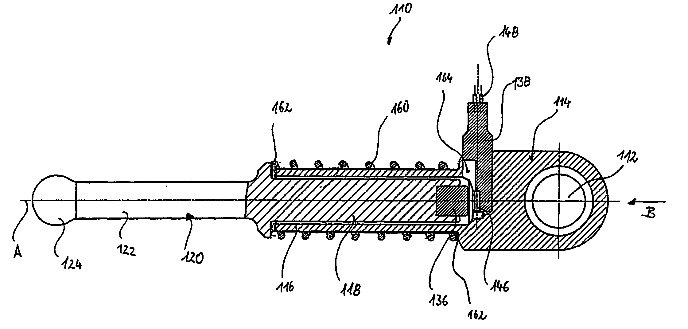
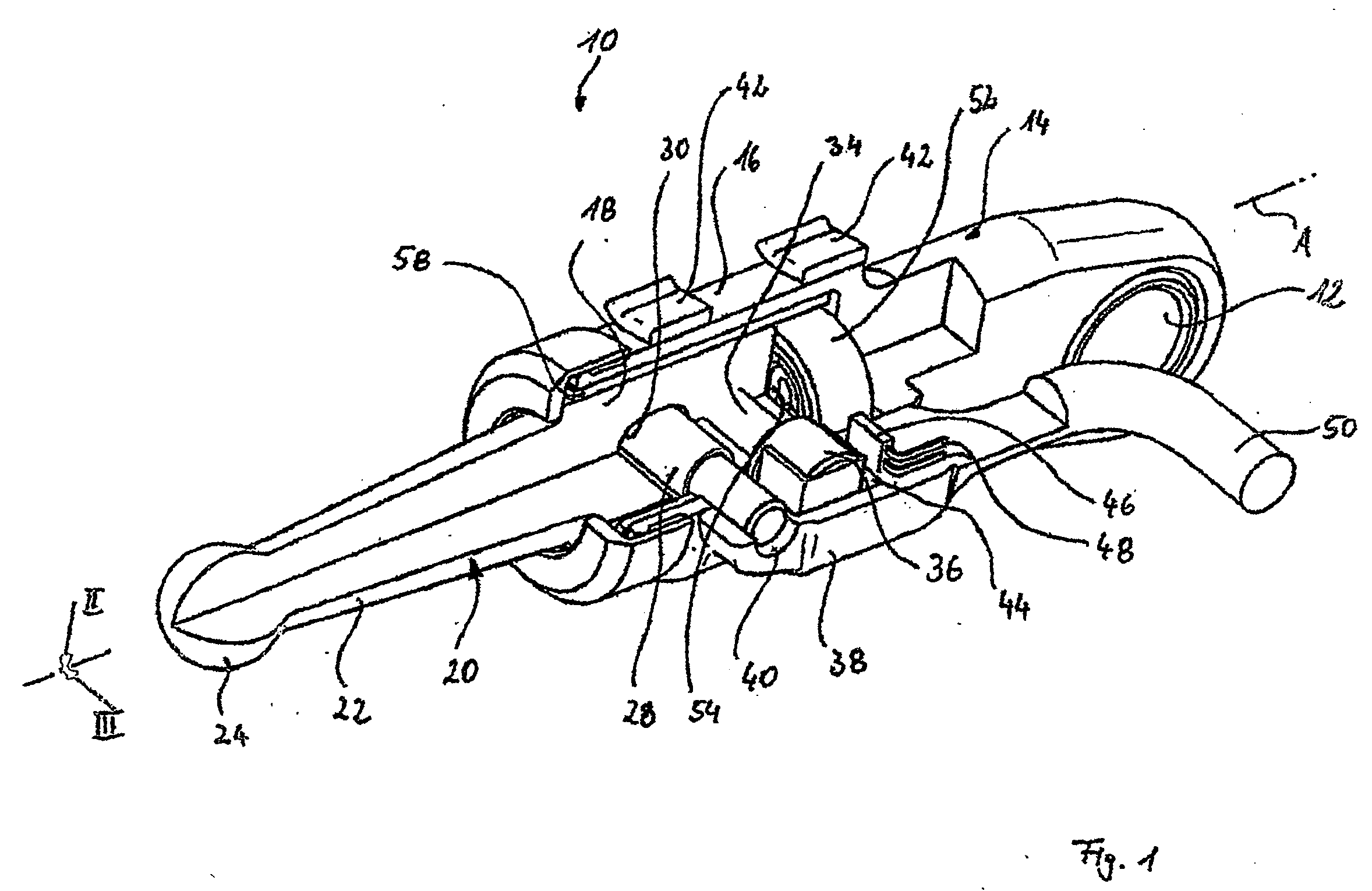
[0023] Represented in FIG. 1, and denoted in general by the reference 10, is a device according to the invention, in the form of a force-admitting element of a brake system for a vehicle. The device 10 is coupled, by means of a seating eye 12, to a brake pedal, which is not shown. The seating eye 12 is realized in a free end of a force take-up element 14. At its other end, the force take-up element 14 has a hollow cylindrical portion 16. Extending into this hollow cylindrical portion is a cylindrical end 18 of a force-transmitting element 20. The force-transmitting element 20 has a shaft 22 which is spherical in form at its free end at 24. The spherical end 24 is connected to the brake system, for example to a brake booster.

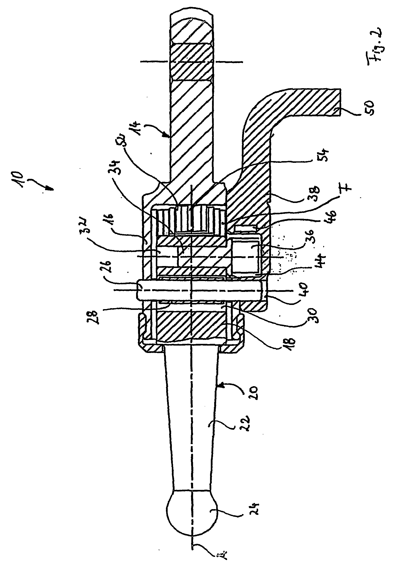
[0024] For the purpose of further describing the device, reference is additionally made to the sectional representations according to FIGS. 2 and 3.

[0025] A guide pin 26, which is fixed in the walls of the hollow cylindrical portion 16, passes through said cyli...


PUM


Abstract

The invention relates to a device for the detection of an actuation force of a brake pedal, comprising a force take-up element coupled to the brake pedal, and a force-transmitting element which is coupled to a brake system and is movable relative to the force take-up element, a sensor device being provided between the force take-up element and the force-transmitting element for the detection of at least one parameter characterizing the actuation force. In the case of this device, provision is made, for the purpose of compact design, whereby the force take-up element and the force-transmitting element are telescopically displaceable relative to one another, and whereby the sensor device is encased by the force take-up element and the force-transmitting element.

Description

[0001] This application is a continuation of International Application No. PCT / EP2004 / 003139 filed Mar. 24, 2004, which claimed priority to German Patent Application No. 103 15 073.0 filed Apr. 2, 2003, the disclosures of which are incorporated herein by reference.BACKGROUND OF THE INVENTION [0002] The present invention relates to a device for the detection of an actuation force of a brake pedal, having the features of the preamble of claim 1. [0003] More recent types of vehicle brake systems are often of such design that they electronically detect a pedal actuation force exerted on a brake pedal, and influence or control a subsequent generation of a braking force in the brake system on the basis of the detected pedal actuation force. There is thus the possibility of brake boosting, in which the pedal actuation force exerted on the brake pedal is introduced into the brake system and boosted by means of a brake booster. Equally, there are solutions in which the pedal actuation force ...

Claims


Application Information

Patent Timeline
IPC IPC(8): B60T17/22B60Q1/44B60T7/04G01L5/22
CPCB60Q1/441G01L5/225B60T7/042
Inventor OHLIG, BENEDIKTGIERING, WILFRIED
Owner LUCAS AUTOMOTIVE GMBH
Why Eureka
Try Eureka