
Focal-plane shutter, and imaging device and electronic apparatus comprising focal-plane shutter

Active Publication Date: 2020-01-09
NIDEC COPAL CORPORATION
View PDF0 Cites 0 Cited by
  • Summary
  • Abstract
  • Description
  • Claims
  • Application Information

AI Technical Summary

Benefits of technology

The invention stops the blade arm from getting worn down.

Problems solved by technology

This sliding of the driving pin and the blade arm causes wear in the blade arm, shortening the service life of the focal plane shutter.
On the other hand, if the driving pin were to be tightly secured to the blade arm, there would be no room that would allow movement of the shutter blade on the blade arm, making smooth travel of the shutter blade difficult.

Method used


Image

  • Focal-plane shutter, and imaging device and electronic apparatus comprising focal-plane shutter
  • Focal-plane shutter, and imaging device and electronic apparatus comprising focal-plane shutter
  • Focal-plane shutter, and imaging device and electronic apparatus comprising focal-plane shutter

Examples


Embodiment Construction

[0024]A focal plane shutter according to an embodiment according to the present invention will be explained in reference to the drawings.

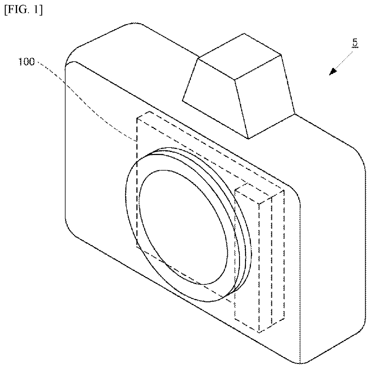
[0025]As illustrated in FIG. 1, the focal plane shutter 100 according to the present embodiment is installed in an imaging device 5 that has an imaging element, an imaging lens, and the like. The imaging element is an image sensor such as, for example, a CCD (charge-coupled device), or a CMOS (complementary metal oxide semiconductor). The imaging device 5 is, for example, a digital camera, a monitoring camera, a vehicle-mounted camera, or the like.

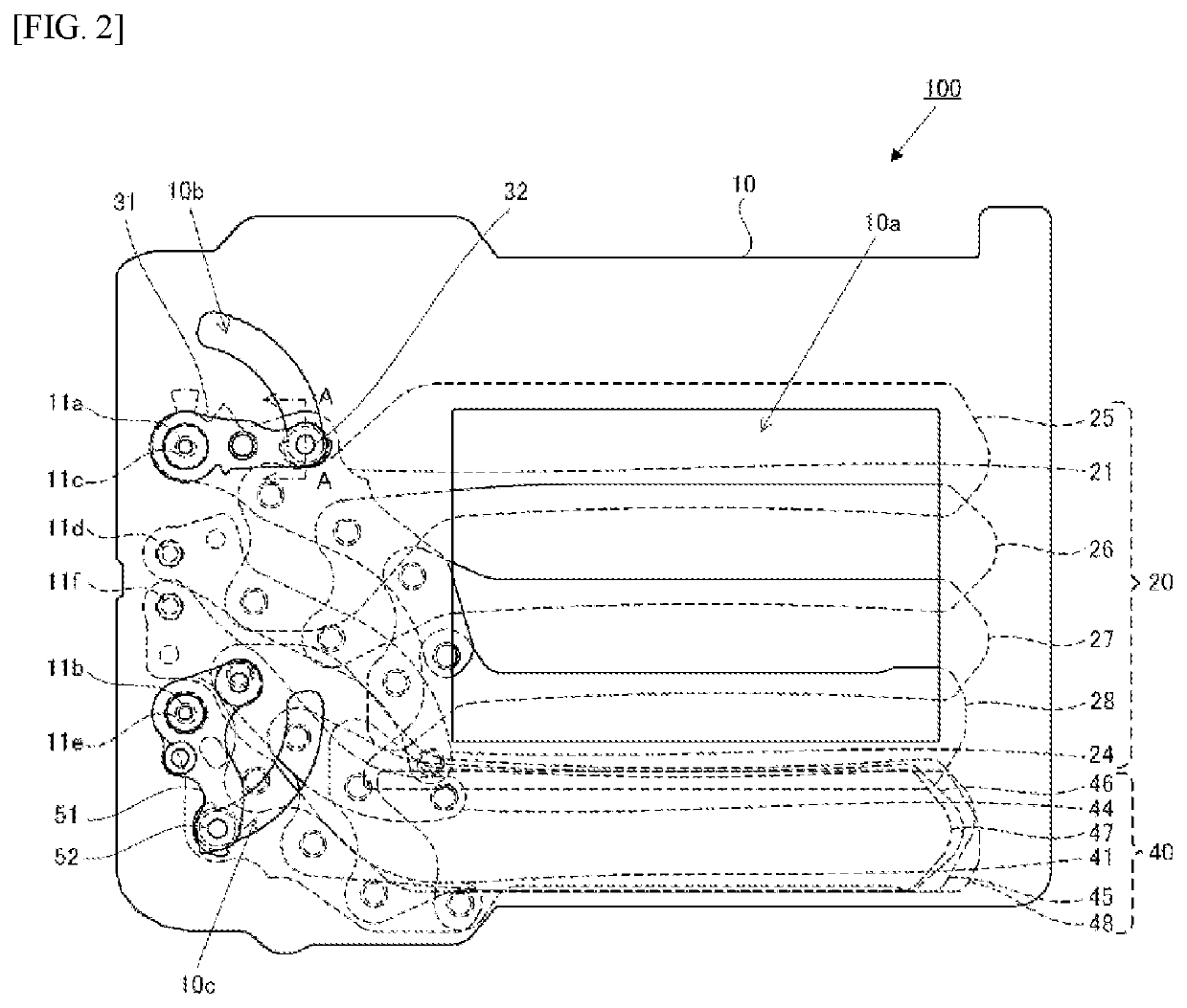
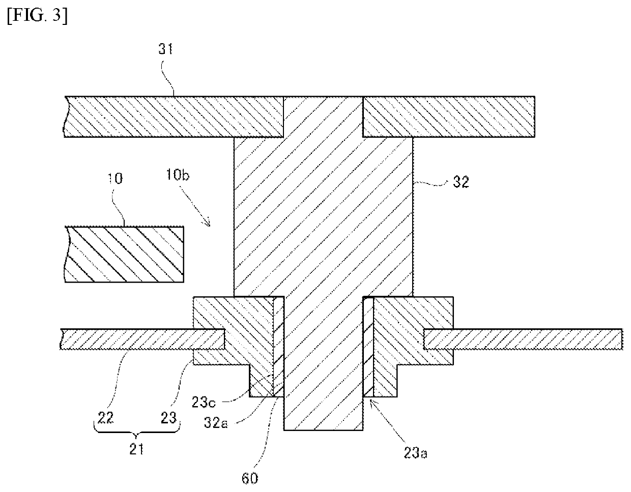
[0026]The structure of the focal plane shutter 100 will be explained in reference to FIGS. 2-5. FIG. 2 depicts the initial state of the focal plane shutter 100 when each member has been set to the position for awaiting imaging. FIG. 3 depicts a cross-section when the focal plane shutter 100 depicted in FIG. 2 is viewed at the section A-A. Note that the explanation in FIG. 2 assumes the front face side is ...


PUM


Abstract

A focal-plane shutter that has a shutter base plate that has an opening; a shutter blade that opens / closes the opening; a blade arm that pivotally supports the shutter blade; and a blade drive member that has a drive pin that is connected to the blade arm. The blade drive member rotates the blade arm so as to drive the shutter blade. The blade arm has a connection hole into which the drive pin is inserted; and a restriction member that is between an inner circumferential surface of the connection hole and an outer circumferential surface of the drive pin and that restricts the movement of the drive pin inside the connection hole.

Description

CROSS-REFERENCE TO RELATED APPLICATIONS[0001]This application is a National Stage of International Application No. PCT / JP2018 / 009673 filed Mar. 13, 2018, which claims priority to Japanese Patent Application No. 2017-049363 filed Mar. 15, 2017. All applications are herein incorporated by reference in their entirety,FIELD OF TECHNOLOGY[0002]The present invention relates to a focal plane shutter, and to an imaging device and electronic apparatus provided therewith.BACKGROUND[0003]There are known focal plane shutters wherein the shutter blades are driven through a blade driving member rotating a blade arm.[0004]For example, Japanese Unexamined Patent Application Publication 2016-161839 discloses a focal plane shutter wherein a blade driving member and a blade arm are connected through insertion of a driving pin of the blade driving member into a connecting hole of the blade arm. In the focal plane shutter of Japanese Unexamined Patent Application Publication 2016-161839, the blade arm i...

Claims


Application Information

Patent Timeline
IPC IPC(8): G03B9/10G03B9/36G03B9/58
CPCH04N5/2254G03B9/10G03B9/36G03B9/58G03B9/42H04N23/55
Inventor KAWAKAMI, KENTA
Owner NIDEC COPAL CORPORATION
Learn More