
Apparatus for receiving stellite DMB and method thereof

a technology of stellite and digital multimedia, applied in the field of satellite digital multimedia broadcasting (dmb), can solve problems such as difficulty in watching a video broadcast on the desired channel, and achieve the effect of minimizing the delay tim

Inactive Publication Date: 2006-03-23
LG ELECTRONICS INC
View PDF6 Cites 13 Cited by
  • Summary
  • Abstract
  • Description
  • Claims
  • Application Information

AI Technical Summary

Benefits of technology

[0015] Therefore, an object of the present invention is to provide a satellite DMB receiving apparatus capable of minimizing a delay time incurred by switching from one video broadcast channel to another, and a method thereof.

Problems solved by technology

However, the related satellite DMB receiving apparatus has the following problem.
Accordingly, when changing from one broadcast channel of the satellite DMB receiving apparatus to another, the user experiences a delay of approximately 5˜8 seconds thereby causing difficulty in watching a video broadcast on the desired channel.

Method used


Image

  • Apparatus for receiving stellite DMB and method thereof
  • Apparatus for receiving stellite DMB and method thereof
  • Apparatus for receiving stellite DMB and method thereof

Examples


first embodiment

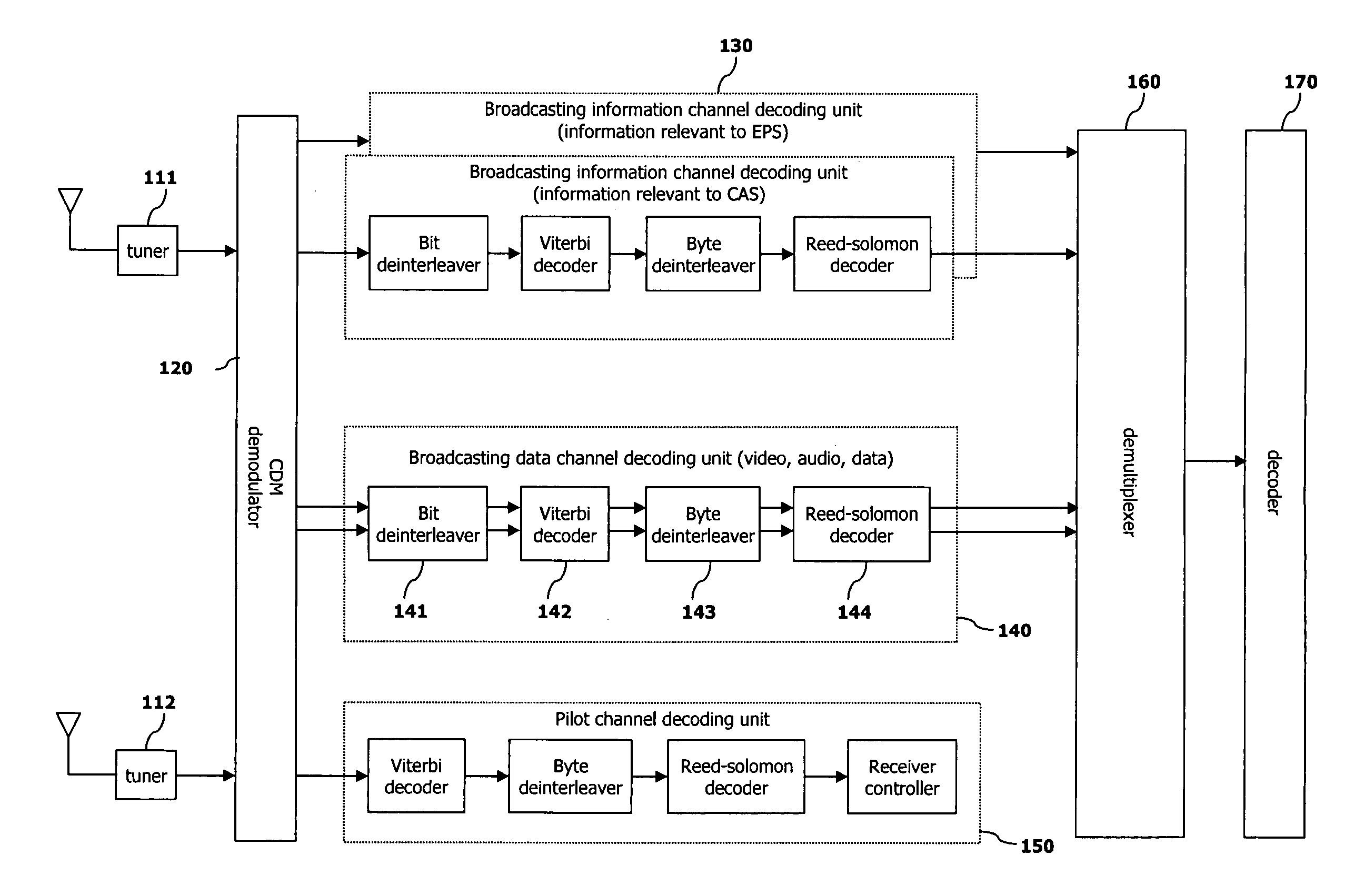
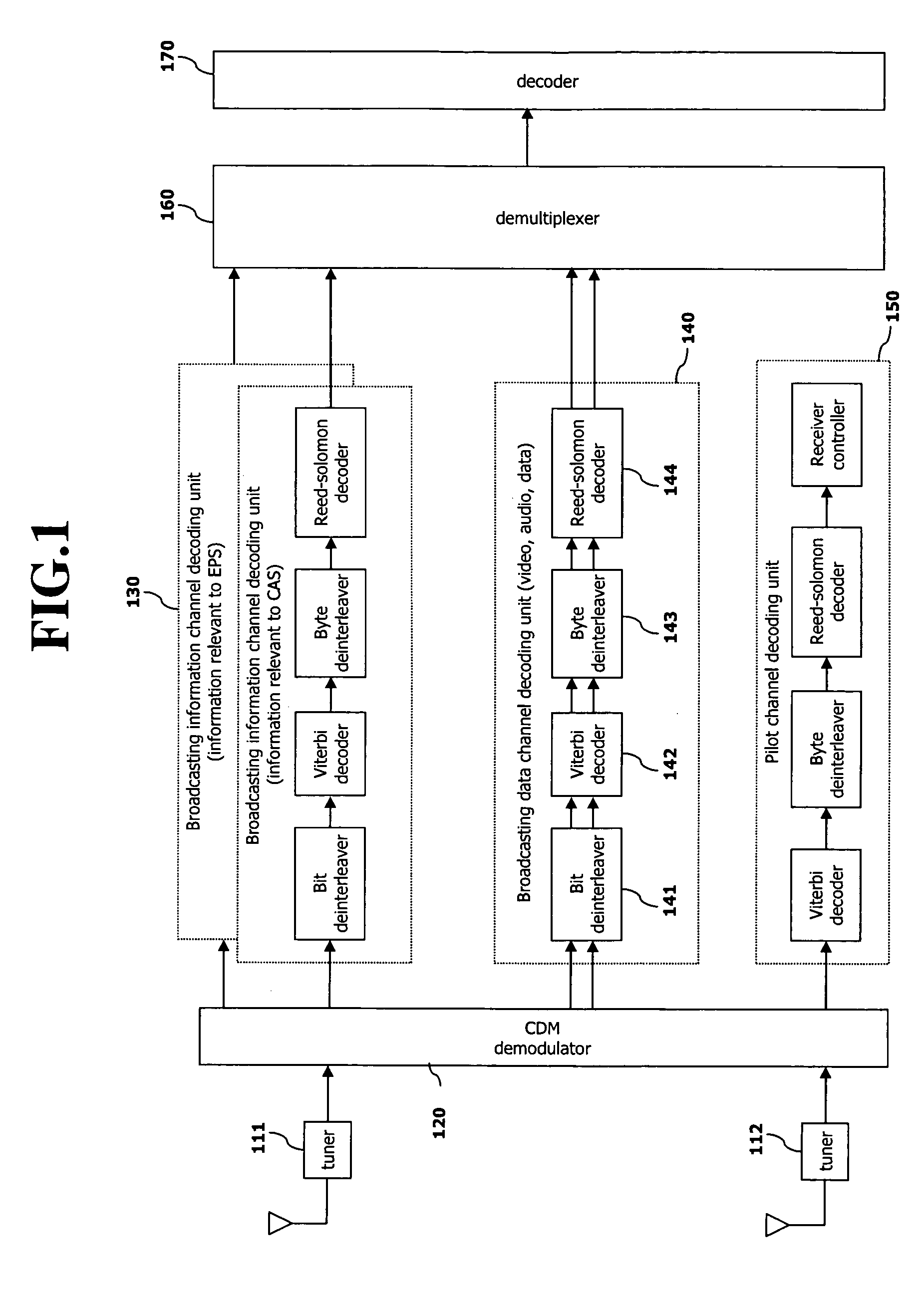
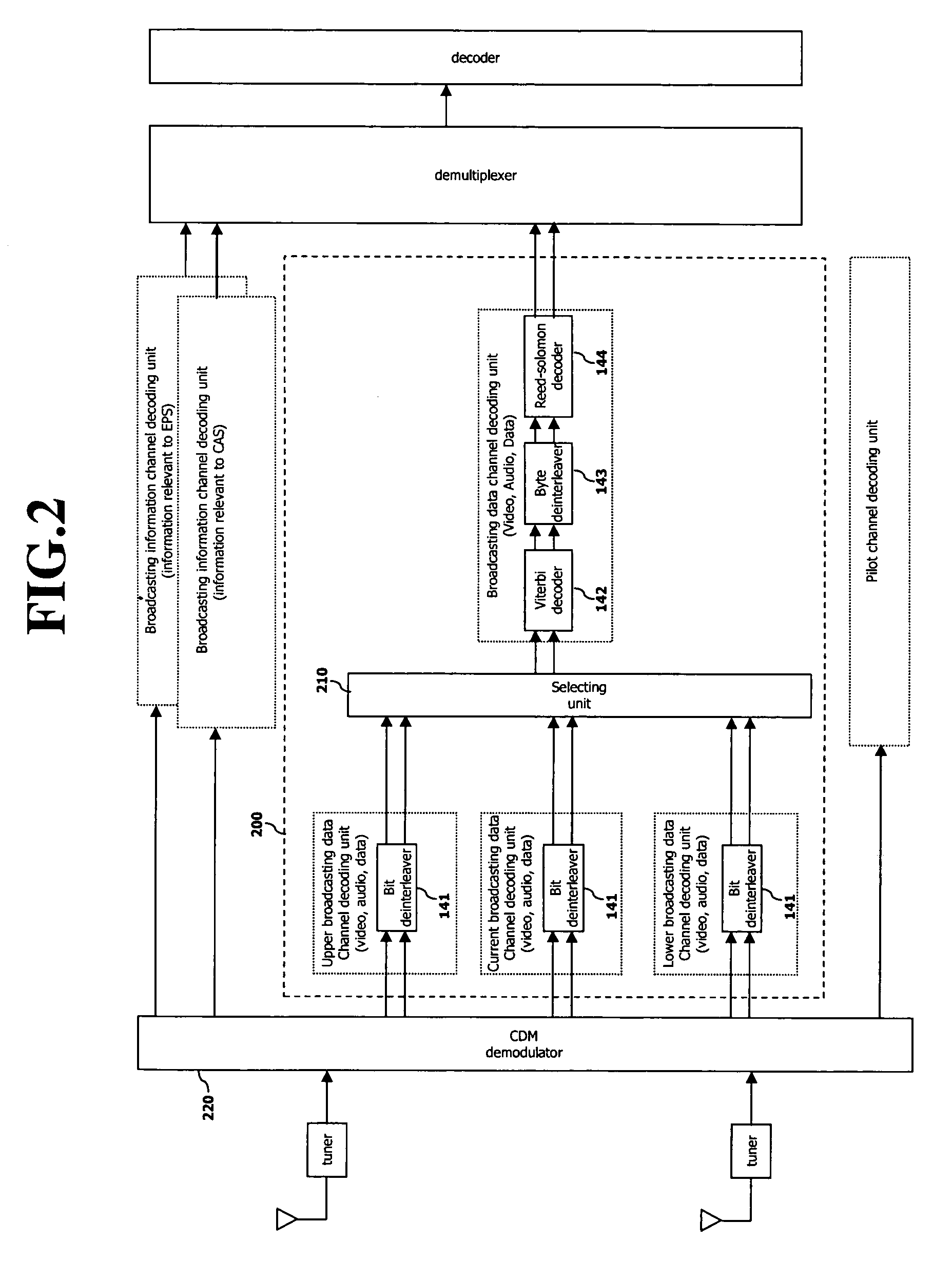
[0030]FIG. 2 is a block diagram showing a satellite DMB receiving apparatus based on a system E according to the present invention, wherein the satellite DMB receiving apparatus according to the present invention is the same as the related art satellite DMB receiving apparatus based on a system E except for a broadcasting data channel decoding unit. Accordingly, the same reference numerals were given to the same components as those of the related art satellite DMB receiving apparatus.

[0031] Referring to FIG. 2, a broadcasting data channel decoding unit 200 of the satellite DMB receiving apparatus according to the present invention comprises: three bit de-interleavers 141 for bit de-interleaving CDM demodulated broadcasting data; a selecting unit 180 for providing bit de-interleaved broadcasting data of one of three broadcast channels selected by a user; and decoders for decoding broadcasting data transmitted from the selecting unit, the decoders further comprising: a viterbi decoder...

second embodiment

[0052] The present invention is the same as the related art shown in FIG. 1 except for the broadcast channel data decoder 200. Accordingly, components having the same reference numerals as those of the related art have the same functions as those of the related art.

[0053] Referring to FIG. 6, the broadcast channel data decoder 200 comprises three broadcasting data channel decoding units 140 for performing a series of decoding processes for each of three broadcast channels, and a selecting unit 210.

[0054] The broadcasting data channel decoding units 140 decode broadcasting data of the current broadcast channel, the upper broadcasting data channel, and the lower broadcasting data channel. The selecting unit 210 extracts only broadcasting data of the broadcast channel selected by the user among broadcasting data decoded by the broadcasting data channel decoding units 140, thereby providing only the broadcasting data of the current broadcast channel to the demultiplexer.

[0055] The br...


PUM


Abstract

Disclosed are an apparatus for receiving a satellite DMB capable of minimizing a video broadcast channel switching time and a method thereof. In the method, time taken to bit de-interleave broadcasting data of the video broadcast channel is reduced thereby to minimize a delay time generated at the time of switching channels. In a satellite DMB receiver having a CDM demodulator for demodulating broadcasting data coded by a Walsh code and having a broadcasting data channel decoding unit for decoding the coded broadcasting data, the satellite DMB receiving apparatus comprises a CDM demodulator for demodulating a Walsh code of at least one broadcast channel, and at least one broadcasting data channel decoding unit for decoding more than one broadcast channel, and a selecting unit for selecting a channel to be viewed by a user.

Description

CROSS-REFERENCE TO RELATED APPLICATIONS [0001] Pursuant to 35 U.S.C. § 119(a), this application claims the benefit of earlier filing date and right of priority to Korean Application No. 71743 / 2004 filed Sep. 8, 2004, the contents of which are hereby incorporated by reference herein in its entirety. FIELD OF THE INVENTION [0002] The present invention relates to satellite digital multimedia broadcasting (DMB), and more particularly, to an apparatus for receiving a satellite DMB based on a system E method capable of minimizing the switching time of changing from one video broadcast channel to another and a method thereof. BACKGROUND OF THE INVENTION [0003] Generally, digital multimedia broadcasting (DMB) is a more enhanced digital broadcasting technique than a digital broadcasting technique for an audio only service, and DMB refers to a communication service for providing an audio service and a video service to a plurality of channels. [0004] DMB provides high quality sound and picture...

Claims


Application Information

Patent Timeline
Patent Type & Authority Applications(United States)
IPC IPC(8): H04N7/20H04L27/22H04B1/707H04N7/173H04H1/00H04H40/90H04J13/18H04N5/44H04N21/426H04N21/435H04N21/438H04N21/61
CPCH04H40/90H04J13/0048H04J13/18H04L1/0054H04L1/0065H04N21/6143H04N7/20H04N21/4263H04N21/4382H04N21/4384H04L1/0071
Inventor CHO, NAM-SHIN
Owner LG ELECTRONICS INC
Learn More