Electronic active lock pin control method for middle phase type continuously variable valve timing system

a technology of electronic active lock pin control and timing system, which is applied in the direction of valve arrangement, machine/engine, output power, etc., can solve the problems of engine stall, reduced power performance, and reduced driving comfor

Active Publication Date: 2016-04-28
HYUNDAI MOTOR CO LTD +1
View PDF1 Cites 0 Cited by
  • Summary
  • Abstract
  • Description
  • Claims
  • Application Information

AI Technical Summary

Benefits of technology

The present invention provides a middle phase type continuously variable valve timing system that uses an electronic active lock pin control method to improve target trackability of the middle phase type CVVT to a general CVVT engine level. The method can minimize a lock pin unlocking delay time depending on lubrication conditions and can perform a pre assist or an assist for unlocking of the lock pin and then perform a phase control depending on the middle phase type CVVT target value. The technical effects are an improved engine performance and efficiency by optimizing the valve timing and optimizing the overall engine performance.

Problems solved by technology

Further, when the unlocking of the lock pin is not permitted, the middle phase type CVVT operation is not permitted, and as a result, drivability may deteriorate and an engine may stall.
An adverse effect due to the lock pin unlocking delay may be improved by performing a middle CVVT assist control for side-force offset after the lock pin is unlocked and then performing the middle phase type CVVT phase control, but a delay time from timing at which the target value of the CVVT is generated to timing at which the CVVT moves occurs at the middle phase type CVVT, and thus a reduction in power performance may not be completely solved.

Method used


Image

  • Electronic active lock pin control method for middle phase type continuously variable valve timing system
  • Electronic active lock pin control method for middle phase type continuously variable valve timing system
  • Electronic active lock pin control method for middle phase type continuously variable valve timing system

Examples


Embodiment Construction

[0028]Reference will now be made in detail to various embodiments of the present invention(s), examples of which are illustrated in the accompanying drawings and described below. While the invention(s) will be described in conjunction with exemplary embodiments, it will be understood that the present description is not intended to limit the invention(s) to those exemplary embodiments. On the contrary, the invention(s) is / are intended to cover not only the exemplary embodiments, but also various alternatives, modifications, equivalents and other embodiments, which may be included within the spirit and scope of the invention as defined by the appended claims.

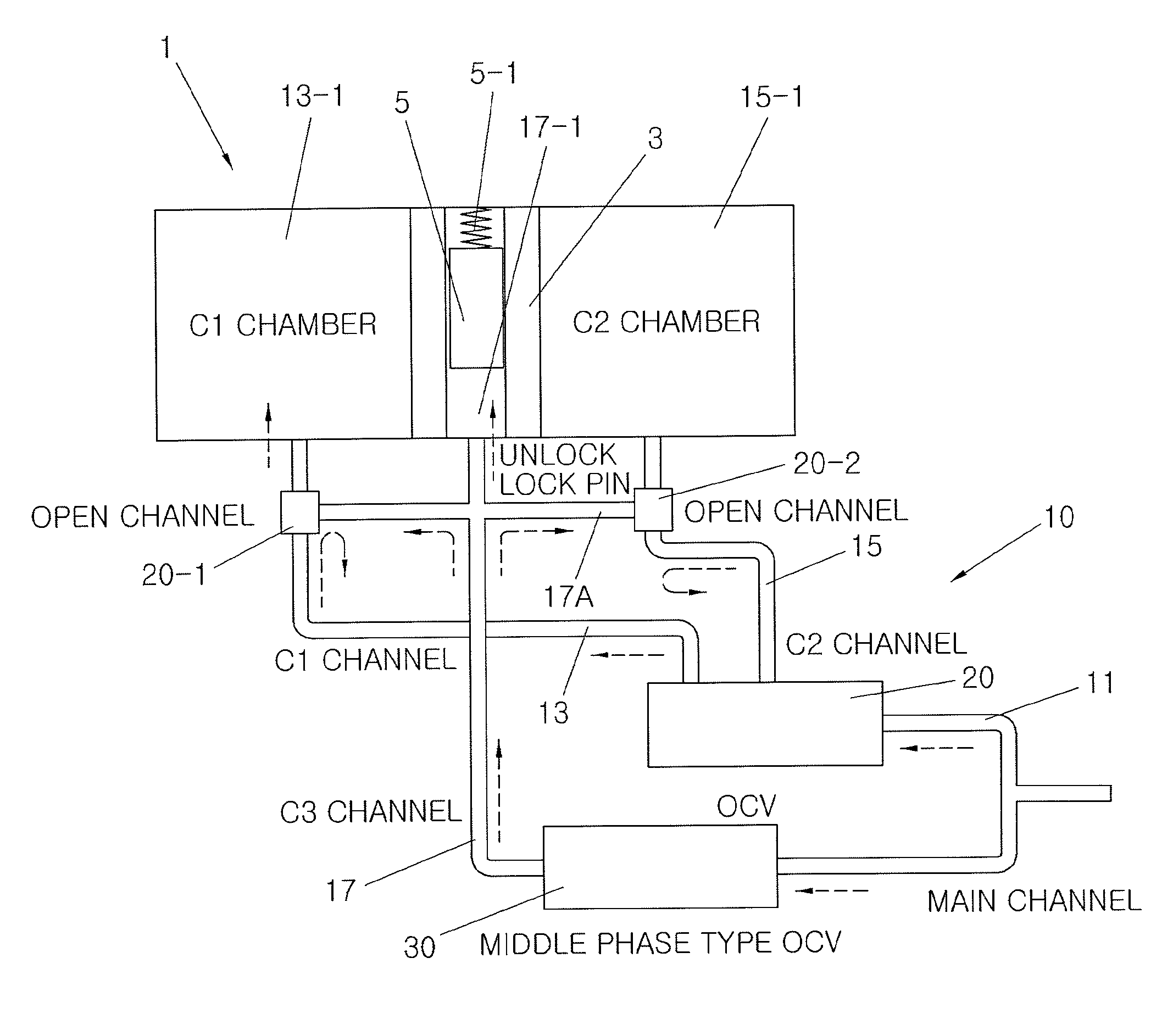
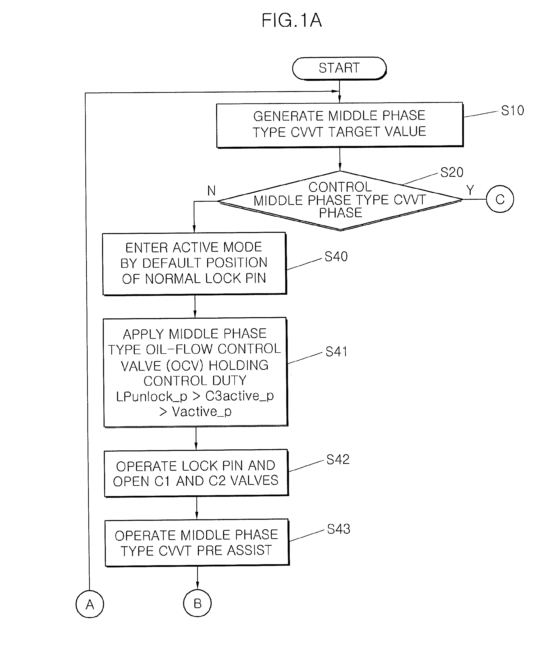
[0029]FIG. 1A and FIG. 1B illustrate a flow chart of an electronic active lock pin control method in accordance with various embodiments of the present invention. As illustrated in FIG. 1A and FIG. 1B, when a middle phase type CVVT target value is generated in an electronic active lock pin control (S10), it is determined whether a...


PUM


Abstract

An electronic active lock pin control method may include checking whether a default position of a lock pin is present, determining whether the checked default position of the lock pin is due to lock pin parking or limphome, entering the default position of the lock pin into an active mode at a time of the lock pin default position by the lock pin parking, while entering the default position of the lock pin into a passive mode at a time of the lock pin default position by the limphome, and performing a phase control mode to track the middle phase type CVVT target value after the passive mode or the active mode.

Description

CROSS-REFERENCE TO RELATED APPLICATIONS[0001]The present application claims priority to Korean Patent Application No. 10-2014-0146259, filed Oct. 27, 2014, the entire contents of which is incorporated herein for all purposes by this reference.BACKGROUND OF THE INVENTION[0002]1. Field of the Invention[0003]Various aspects of the present invention relate to a middle phase type continuously variable valve timing system (hereinafter, referred to as middle phase type CVVT), and more particularly, to a middle phase type continuously variable timing system using an electronic active lock pin control method which may improve target trackability of the middle phase type CVVT to a general CVVT engine level by performing lock pin unlocking and a phase control while generating a middle phase type CVVT target value.[0004]2. Description of Related Art[0005]Generally, middle phase type CVVT has rapider system responsiveness and a wider use area of a cam as compared with CVVT, by controlling a posi...

Claims


Application Information

Patent Timeline
Patent Type & Authority Applications(United States)
IPC IPC(8): F01L1/344
CPCF01L2001/34426F01L1/3442F01L2001/34463F01L2800/01F01L1/34F01L1/344F01L1/46F01L13/00F01M1/16F02D13/02F01L2001/34453
Inventor KIM, SUNG-JOO
Owner HYUNDAI MOTOR CO LTD
Why Eureka
Try Eureka