AM demodulator

a demodulator and receiver technology, applied in the field ofam receivers, can solve the problems of less attractive hardware implementation, and achieve the effects of low cost, less attractive hardware implementation, and cost prohibitive software radio implementation

Inactive Publication Date: 2006-03-23
QUALCOMM INC
View PDF5 Cites 2 Cited by
  • Summary
  • Abstract
  • Description
  • Claims
  • Application Information

AI Technical Summary

Benefits of technology

[0003] Despite the fact that the AM receiver is almost a century old the software radio implementation is still cost prohibitive. Currently, AM receivers are implemented in hardware, employing AM / FM chips at record low cost. A simplified block diagram of a conventional AM receiver is illustrated in FIG. 1. However, in a multi protocol communication hand held device, the hardware implementation becomes less attractive due to extra cost and PC board area consumed. The most attractive alternative for multi protocol communication devices is provided by the Software Defined Radio (SDR). The SDR has the ability to execute multiple communication protocols in the same processor but requires a different RF front end for each of them. As the processor capabilities evolve to higher MIPS, the border between analog and digital components moves closer to the antenna.
[0004] The hardware architecture of the present AM receiver uses fewer hardware components and allows an efficient software implementation by reducing the MIPS required. It provides both flexibility and low power consumption. A group of the AM receiver functions, including filtering and demodulation, are implemented in software.

Problems solved by technology

Despite the fact that the AM receiver is almost a century old the software radio implementation is still cost prohibitive.
However, in a multi protocol communication hand held device, the hardware implementation becomes less attractive due to extra cost and PC board area consumed.

Method used


Image

  • AM demodulator
  • AM demodulator
  • AM demodulator

Examples


Embodiment Construction

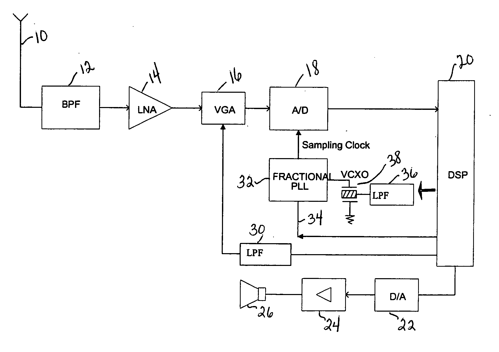
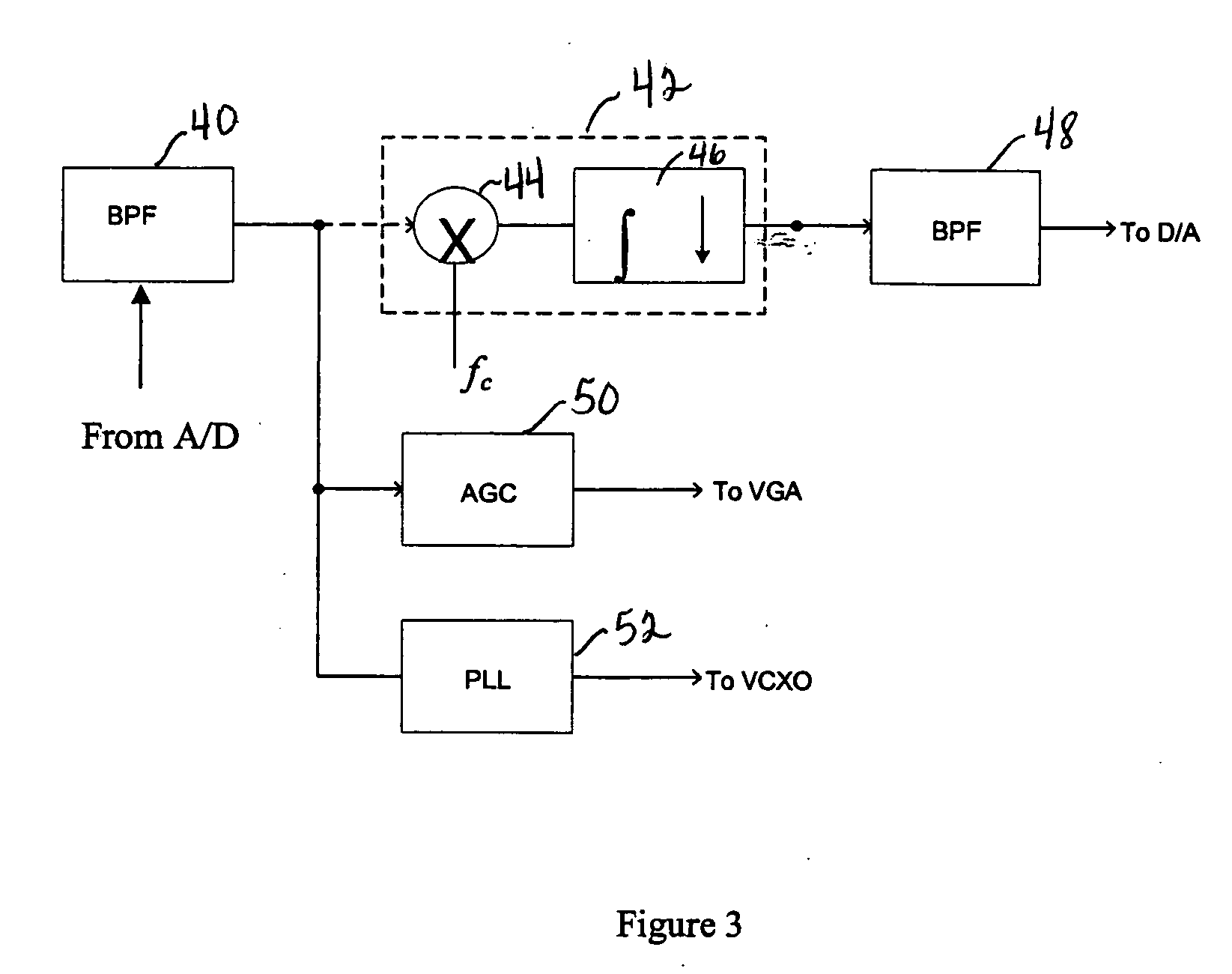
[0014] The present receiver is a reduced MIPS software implementation of a conventional AM receiver. By using a variable sampling rate scheme such that the sampling rate is coherent with the received carrier frequency, the complexity of several AM receiver blocks, associated with the demodulation process, including the down conversion block, can be significantly reduced and executed in software. The benefit of the reduced complexity AM receiver translates in low cost as well as low power consumption, thereby enabling its integration into hand held devices such as mobile phones, PDAs or multi-protocol communication devices. In the present architecture, all functions associated with the AM receiver, including most of the filtering and the demodulation, are executed in software, for example using two threads of the Sandbridge Technologies multithreaded SB9600 processor.

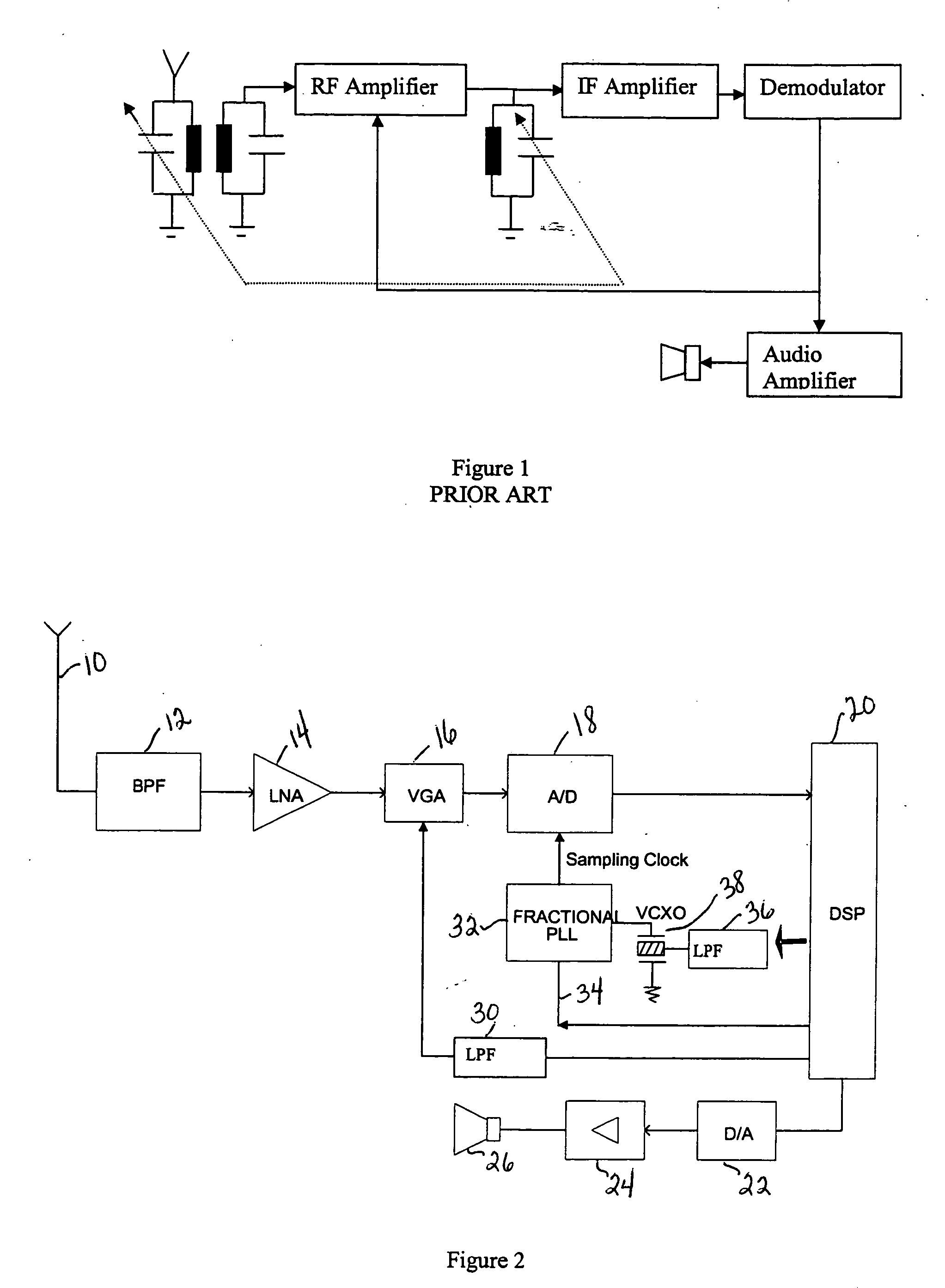
[0015] Hardware components of an AM receiver designed for software implementation is illustrated in FIG. 2. The signa...


PUM


Abstract

An amplitude modulation receiver including an antenna for receiving a signal and an input filter connected to the antenna. A variable gain amplifier is connected to the input filter and is responsive to a gain control signal. An A / D converter is connected to the variable gain amplifier and is responsive to a sampling signal and provides a sampled digital signal. A D / A converter receives a demodulated signal and provides an analog output signal. A controller receives and demodulates the sampled digital signal from the A / D converter, generates the gain control signal for the variable gain amplifier, generates the sampling signal for the A / D converter, and provides the demodulated signal to the D / A converter. The demodulation and generation of the gain control signal and the sampling signal are performed in software.

Description

[0001] The present application is a division of U.S. patent application Ser. No. 10 / 400,506 filed Mar. 28, 2003, the benefit of which is claimed and which is incorporated herein by reference.BACKGROUND AND SUMMARY OF THE INVENTION [0002] The present invention relates generally to AM receivers and more specifically to a receiver capable of software implementation of varies elements in AM receivers. [0003] Despite the fact that the AM receiver is almost a century old the software radio implementation is still cost prohibitive. Currently, AM receivers are implemented in hardware, employing AM / FM chips at record low cost. A simplified block diagram of a conventional AM receiver is illustrated in FIG. 1. However, in a multi protocol communication hand held device, the hardware implementation becomes less attractive due to extra cost and PC board area consumed. The most attractive alternative for multi protocol communication devices is provided by the Software Defined Radio (SDR). The SDR...

Claims


Application Information

Patent Timeline
Patent Type & Authority Applications(United States)
IPC IPC(8): H04B1/18H04L27/16H04B1/16H03G3/30H04B1/28
CPCH03G3/3036H03G3/3052H04B1/28H04B1/0021H04B1/0003H04B1/16H04L27/06
Inventor IANCU, DANIEL
Owner QUALCOMM INC
Why Eureka
Try Eureka