
Oxidant injection method

Active Publication Date: 2006-03-16
AIR PROD & CHEM INC
View PDF15 Cites 37 Cited by
  • Summary
  • Abstract
  • Description
  • Claims
  • Application Information

AI Technical Summary

Problems solved by technology

Many methods have been suggested for reducing nitrogen oxides (NOx) emissions from regenerative glass furnaces, but few have been actually implemented.
Both approaches have limitations due to the lowering of the furnace efficiency, and production rate, and are often difficult to implement due to furnace design considerations.
Pollution control techniques usually result in added cost.

Method used


Image

  • Oxidant injection method
  • Oxidant injection method
  • Oxidant injection method

Examples


Embodiment Construction

[0021] The term “oxidant” is used to mean air, or enriched air (which is air having a higher percentage of oxygen than in ambient air.

[0022] The term “enriched air” means a gas stream comprising greater than 21% by volume oxygen. (21% oxygen by volume is the amount of oxygen in ambient air.) It can be from any source, and includes vent stream, an oxygen-rich gas stream from a vacuum or pressure swing adsorbant apparatus (VSA or PSA), or cryogenic separation unit, or another separation mechanism, of any purity, alone or mixed with air.

[0023] The term “vent stream” means the exiting gas stream (that is not the product gas stream) from a vacuum or pressure swing adsorbant apparatus (VSA or PSA), or cryogenic separation unit, or another air separation mechanism that is primarily used to make, that is, separate a product gas, e.g. nitrogen or another gas, from air.

[0024] The term “fuel” means gaseous fuels, such as natural gas, propane, and refinery fuels (mixture of combustable gases...


PUM

PropertyMeasurementUnit
Ratioaaaaaaaaaa

Abstract

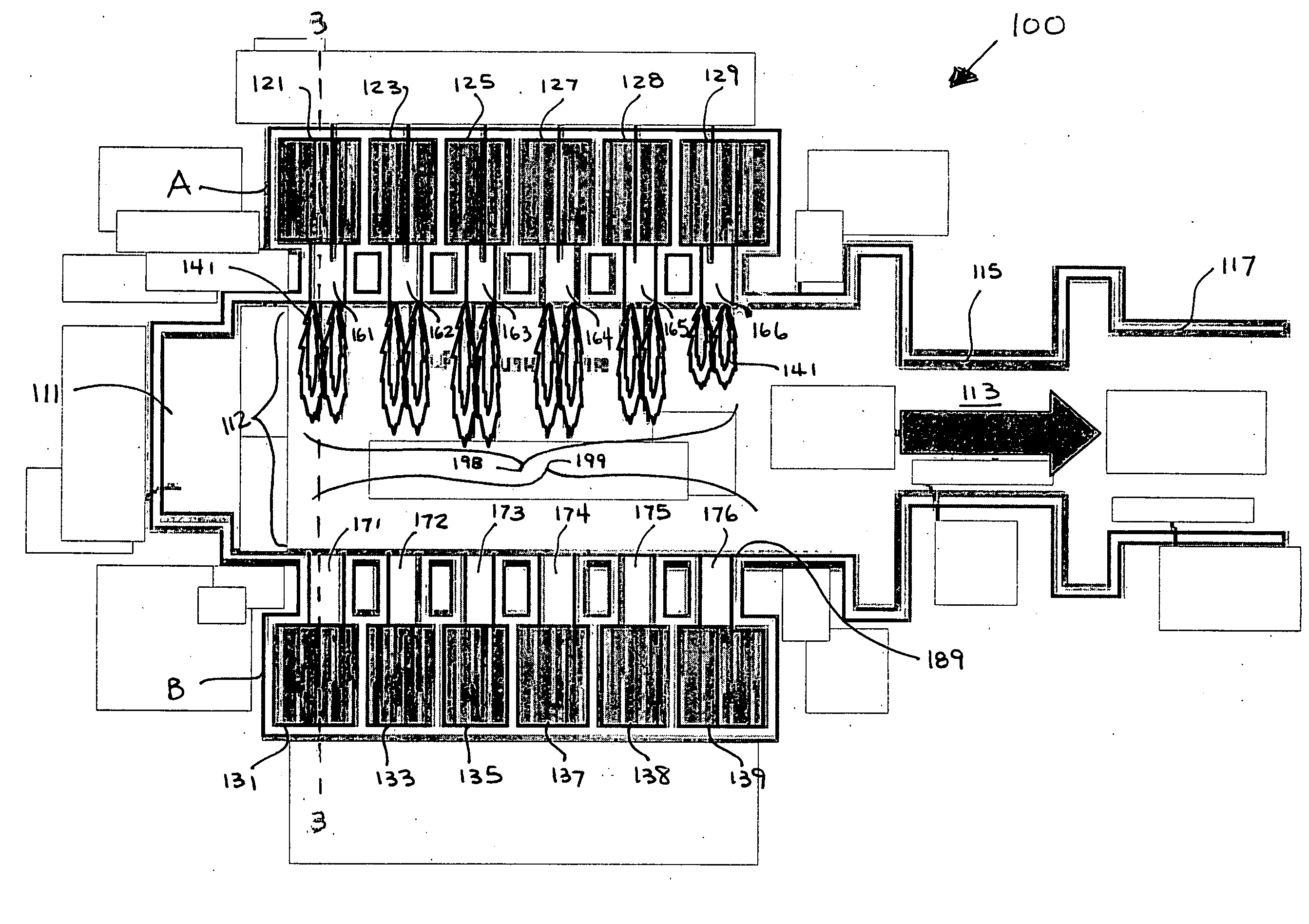
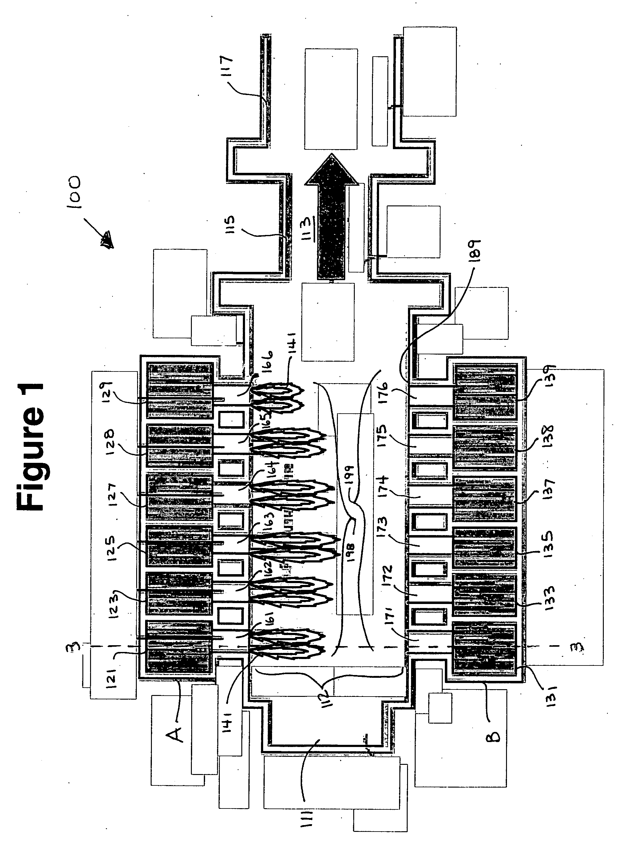
A method of combustion in a furnace comprising a firing zone and an exhaust zone, three oxidants and fuel comprising the steps of: introducing fuel into said firing zone; introducing a first oxidant into the firing zone; introducing a second oxidant into the firing zone; and introducing a third oxidant into the exhaust zone; wherein during said step of introducing a first oxidant, the step of introducing a second oxidant, and the step of introducing a third oxidant occur.

Description

[0001] This nonprovisional application claims the benefit of a provisional application U.S. Ser. No. 60 / 609113 filed on Sep. 10, 2004, incorporated herein by reference.BACKGROUND OF THE INVENTION [0002] Regenerative glass furnaces operate at very high process temperatures due to a high temperature air preheat level. For achieving higher thermal efficiency, the combustion air is preheated to approximately 2400° F. in ceramic regenerators before reacting with fuel inside the furnace interior. Many methods have been suggested for reducing nitrogen oxides (NOx) emissions from regenerative glass furnaces, but few have been actually implemented. [0003] During high temperature combustion as observed in regenerative glass furnaces, NOx is formed primarily by thermal oxidation of nitrogen in combustion air—denoted as thermal NOx. Generally, thermal NOx depends on time-temperature history of the flame and increases with increasing peak flame temperatures. [0004] The primary methods of reducin...

Claims


Application Information

Patent Timeline
IPC IPC(8): F23N1/02F27D99/00
CPCC03B5/235C03B5/2353F23C6/045Y02E20/344F23C2900/06041F23L2900/07005F23L2900/07007F23C7/02Y02E20/34Y02P40/50C03B5/04F23D14/32B01J15/00C03B5/00
Inventor JOSHI, MAHENDRA LADHARAMHABEL, MICHAEL E.LIEVRE, KEVIN ALAN
Owner AIR PROD & CHEM INC
Learn More