Thermally controlled fluidic self-assembly

Inactive Publication Date: 2006-03-16
EASTMAN KODAK CO
View PDF30 Cites 92 Cited by
  • Summary
  • Abstract
  • Description
  • Claims
  • Application Information

AI Technical Summary

Benefits of technology

[0021] In still another aspect of the invention, a method is provided for arranging at a pattern of at least three colored micro-components, using a support having an arrangement of binding sites adapted to receive the colored micro- components. In accordance with the method, a first fluid that increases viscosity in response to heat, is heated in a pattern that corresponds to binding sites for a second and a third colored micro-components are to be located so that each binding site for a second and a third colored micro-component is blocked by a portion of the first fluid having an increased viscosity and the support is exposed to a first slurry containing the first colored micro-structure and a first carrier fluid so that the first colored micro-structures can assemble to binding sites that are not blocked and any non-assembled first colored micro-components are removed from the support and allowing the portions of the first fluid having an increased viscosity to cool so that they do not block the binding sites for the second and third colored micro-components. A second fluid that increases viscosity in response to heat, is heated in a second pattern that corresponds to binding sites for the third colored micro-structures so that each binding site for each third colored micro-component is blocked by a portion of the second fluid having an increased viscosity and the support is exposed to a second slurry containing the second colored micro-components and a second carrier fluid so that the second colored micro-structures can assemble to binding sites that are not occupied by the first colored micro-components and that are not blocked. Any non-assembled second colored micro-components are removed from the support and the portions of the second fluid having an increased viscosity are allowed to cool so that they do not block the binding sites for the third colored binding sites. The support is further exposed to a third slurry containing the third colored micro-components and a third carrier fluid so that the third colored micro-components can assemble to binding sites to are not occupied by the first colored micro-components and the second micro-components.
[0022] In still another aspect of the invention, an apparatus for assembling a micro-assembled structure on a support having binding sites thereon is provided. The apparatus has a fluid source adapted to apply a first fluid having first micro- components therein onto the support, the first micro-components being adapted to engage the binding sites and the first fluid being of a type that increases viscosity in response to heat; and an energy source adapted to apply energy to heat the first fluid source to increase the viscosity of the first fluid proximate to the selected binding sites to inhibit micro-components from engaging the selected binding sites.
[0023] In yet another aspect of the invention, an apparatus for assembling a structure using a support having binding sites thereon is provided. The apparatus has a means for providing onto the support a first fluid of a type that increases viscosity in response to heat, a means for selectively heating the first fluid proximate to selected binding sites and a means for exposing the support to a first slurry of a carrier fluid having a first type of micro-components therein, so that the first type of micro-components can engage the non-selected binding sites.

Problems solved by technology

Accordingly, such deterministic methods are difficult to apply in a cost effective manner.
However, it will be appreciated that this method requires the precise placement of drops of liquid 34 on substrate 10 and does not necessarily provide the discrimination useful in the assembly of components having multiple types of micro-components.
However, high cost is encountered in providing the arrays of disks on the substrate.
Further such methods are typically limited to applications wherein the micro-assembled structures being assembled each have magnetic characteristics that permit the use of magnetic forces in this fashion.
However, the use of electrostatically based fluidic micro-assembly can involve high cost associated with providing addressable electrode structures required for long range transport of micro-components by dielectrophoresis.
However, the constraints of surface etching techniques, micro-component formation techniques, cost, electrical function, and orientation limit the number of shape configurations that are available for use in discrimination, which in turn limits the number of different components that can be placed on the substrate using such a process.
While this approach provides a high degree of differentiation high cost may be encountered in patterning the DNA or ligands on the substrate.

Method used


Image

  • Thermally controlled fluidic self-assembly
  • Thermally controlled fluidic self-assembly
  • Thermally controlled fluidic self-assembly

Examples


Embodiment Construction

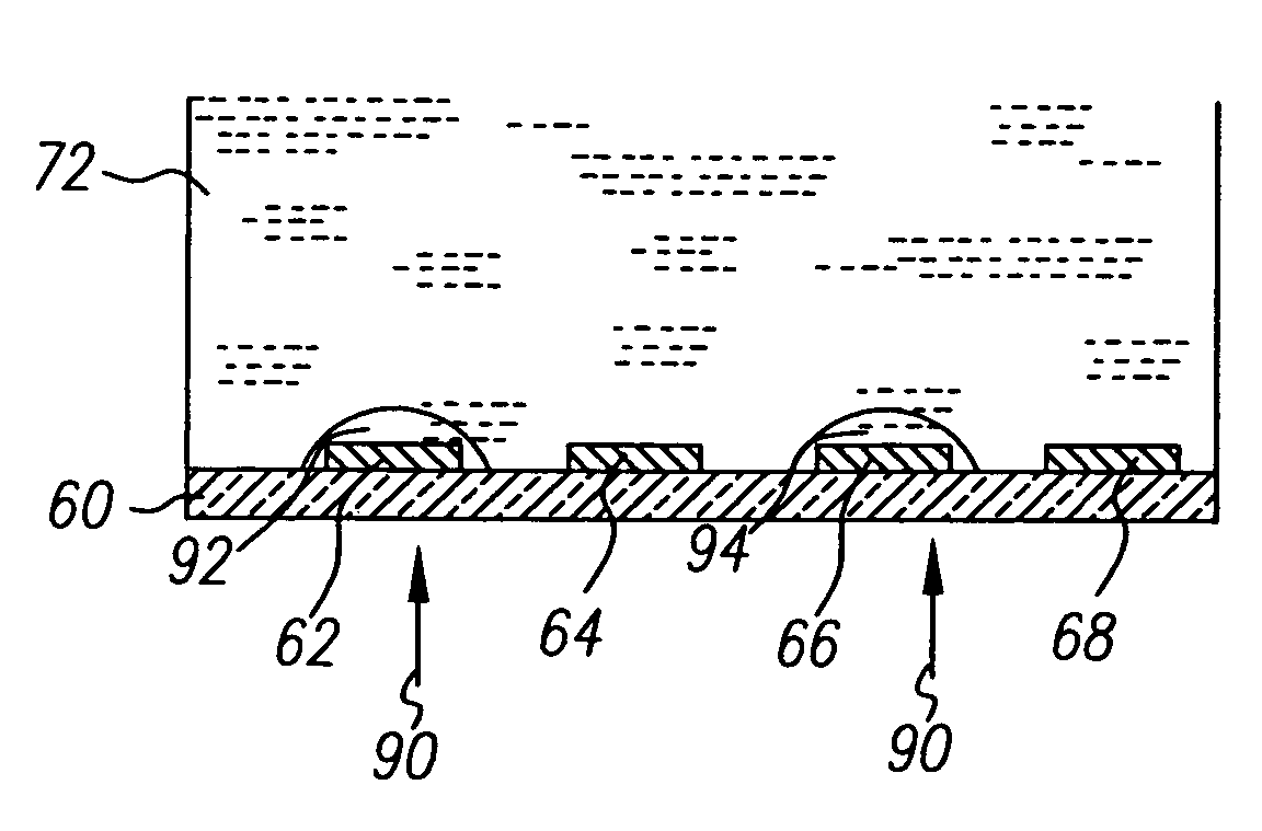
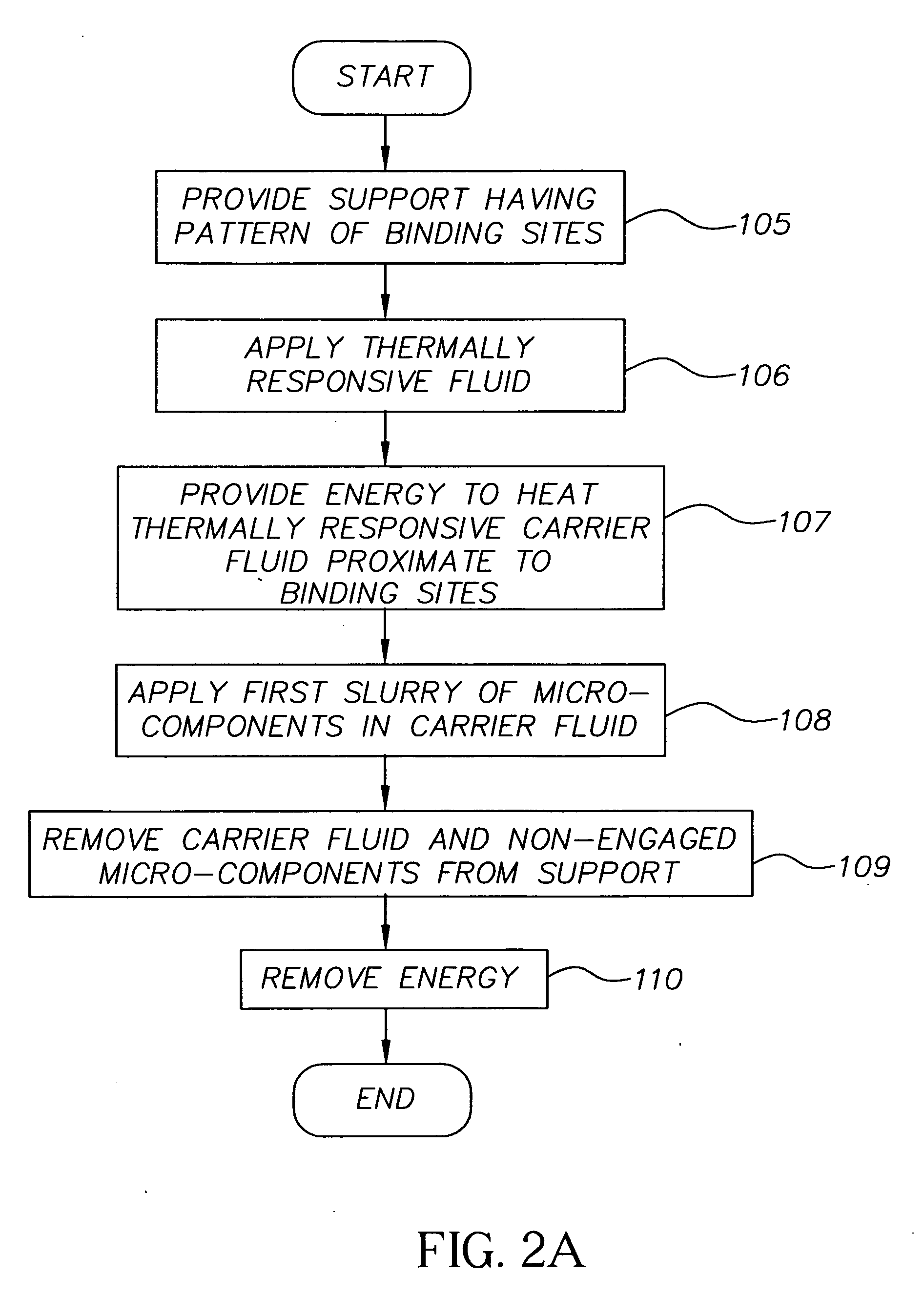
[0047]FIG. 2a is a flow diagram of one embodiment of the method of invention. FIGS. 3a and 3b illustrates one example of fluidic self-assembly in accordance with the method of FIG. 2a. As is shown in FIG. 3a, a support 60 is provided (step 105). Support 60 can be, but is not limited to, a flexible support such as polyethylene terephthalate, cellulose acetate, polyethylene, polycarbonate, polymethyl methacrylate, polyethylene napthalate, metal foils, cloth, fabric, woven fiber or wire meshes or rigid supports such as glass and silicon.

[0048] Support 60 has pattern of binding sites shown in FIGS. 3a-3c as binding sites 62, 64, 66 and 68. Each binding site 62, 64, 66 and 68 is adapted so that a micro-component can be assembled thereon, such as by shaping binding sites 62, 64, 66 and 68 to receive the micro-component. Alternatively, support 60 can have binding sites 62, 64, 66 and 68 that are adapted to engage micro-components using, for example, shape matching, magnetic force, electri...


PUM


Abstract

Methods and apparatuses are provided for assembling a structure on a support having a pattern of binding sites. In accordance with the method, a first fluid is provided on the surface of the support with the first fluid being of a type that that increases viscosity when heated, the first fluid having first micro-components suspended therein each adapted to engage the binding sites. The first fluid proximate to selected binding sites is heated to increase the viscosity of the responsive fluid proximate to the selected binding sites so that the first micro-components suspended in the first fluid are inhibited from engaging the selected binding sites.

Description

CROSS-REFERENCE TO RELATED APPLICATIONS [0001] This application is related to U.S. Ser. No. [Attorney Docket No. 88327], entitled THERMALLY CONTROLLED FLUIDIC SELF-ASSEMBLY METHOD AND SUPPORT, in the names of Daniel D. Haas et al.; and U.S. Ser. No. [Attorney Docket No. 88328], entitled THERMALLY CONTROLLED FLUIDIC SELF-ASSEMBLY METHOD AND CONDUCTIVE SUPPORT, in the names of Theodore K. Ricks et al., all filed concurrently herewith.FIELD OF THE INVENTION [0002] The present invention relates to methods for fluidic micro-assembled structure and, in particular, to methods and apparatuses for selective fluidic assembly of micro-components can be performed. BACKGROUND OF THE INVENTION [0003] Micro-assembled devices offer the promise of an entirely new generation of consumer, professional, medical, military, and other products having features, capabilities and cost structures that cannot be provided by products that are formed using conventional macro-assembly and macro-fabrication method...

Claims


Application Information

Patent Timeline
IPC IPC(8): B05D3/02B05D3/06H01L21/50
CPCH01L24/86H01L2924/12041H01L25/0655H01L25/0753H01L25/50H01L2224/7965H01L2224/95085H01L2224/95136H01L2224/95146H01L2924/01002H01L2924/0101H01L2924/01013H01L2924/01015H01L2924/01018H01L2924/01027H01L2924/01029H01L2924/01049H01L2924/01052H01L2924/01057H01L2924/0106H01L2924/01074H01L2924/01082H01L2924/10329H01L2924/14H01L2924/15155H01L2924/15165H01L2924/19041H01L2924/19042H01L2924/19043H01L2924/3025H01L24/95H01L2224/95145H01L2924/01005H01L2924/01006H01L2924/01019H01L2924/01021H01L2924/01033H01L2924/01084H01L2924/15153H01L2924/12042H01L2924/00
Inventor SHARMA, RAVIHAAS, DANIEL D.RICKS, THEODORE K.
Owner EASTMAN KODAK CO
Why Eureka
Try Eureka