
Test device and method for laser alignment calibration

Active Publication Date: 2006-03-16
TAIWAN SEMICON MFG CO LTD
View PDF9 Cites 15 Cited by
  • Summary
  • Abstract
  • Description
  • Claims
  • Application Information

AI Technical Summary

Benefits of technology

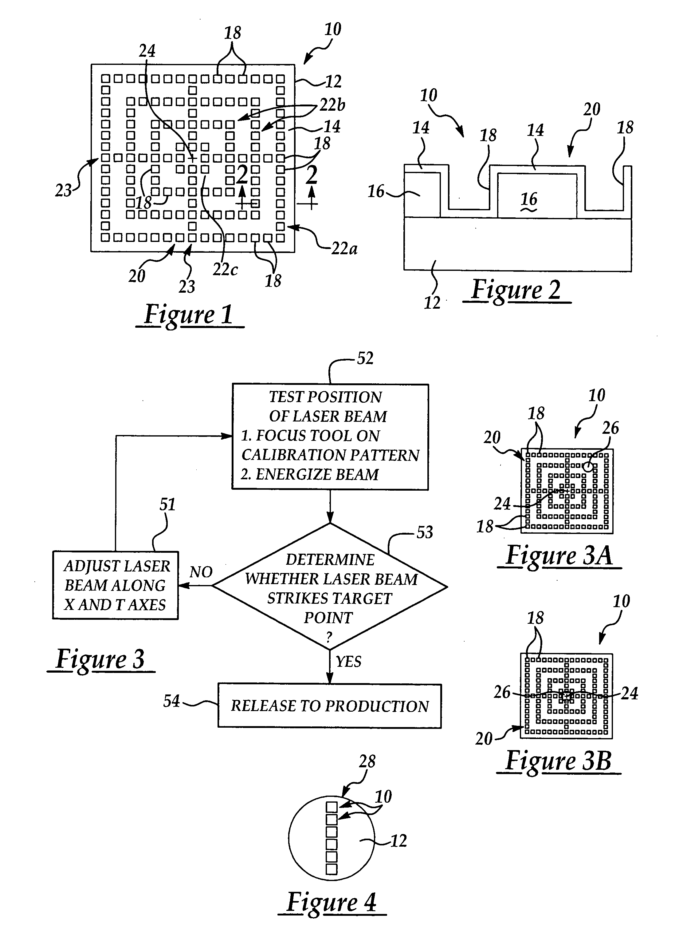
[0013] In accordance with these and other objects and advantages, the present invention is generally directed to a novel test device and method for calibrating the alignment of a laser beam emitted from a laser metrology tool with respect to a target area on a substrate. The test device includes a substrate on which is provided a laser-sensitive material that is easily damaged, ablated, melted, burned or otherwise changed in appearance by direct impingement of the laser beam thereon. A calibration pattern is provided on the laser-sensitive material and includes a target point which may be at the center of the calibration pattern and represents the desired alignment spot of the laser beam with respect to a target area on actual substrates to be measured.

Problems solved by technology

The laser-sensitive material on the test device is damaged, ablated, melted, burned or otherwise changes in appearance to reveal the actual strike position of the laser beam with respect to the target point.

Method used


Image

  • Test device and method for laser alignment calibration
  • Test device and method for laser alignment calibration

Examples


Embodiment Construction

[0025] The present invention includes a novel test device and a method for calibrating the alignment of a laser beam emitted from a laser metrology tool with respect to a target area on a substrate, using the test device. The test device typically includes a substrate on which is provided a laser-sensitive material that is easily damaged, ablated, melted or burned, or otherwise changes appearance by direct impingement of the laser beam on the material. A calibration pattern is provided in the laser-sensitive material. A target point, which represents the desired alignment spot of the laser beam with respect to a target area on actual substrates to be measured, is provided in the center of the calibration pattern or in some other location on the calibration pattern.

[0026] In a typical embodiment, the test device includes a substrate on which is deposited a laser-sensitive material. The calibration pattern is defined by multiple pattern openings which extend into the laser-sensitive ...


PUM


Abstract

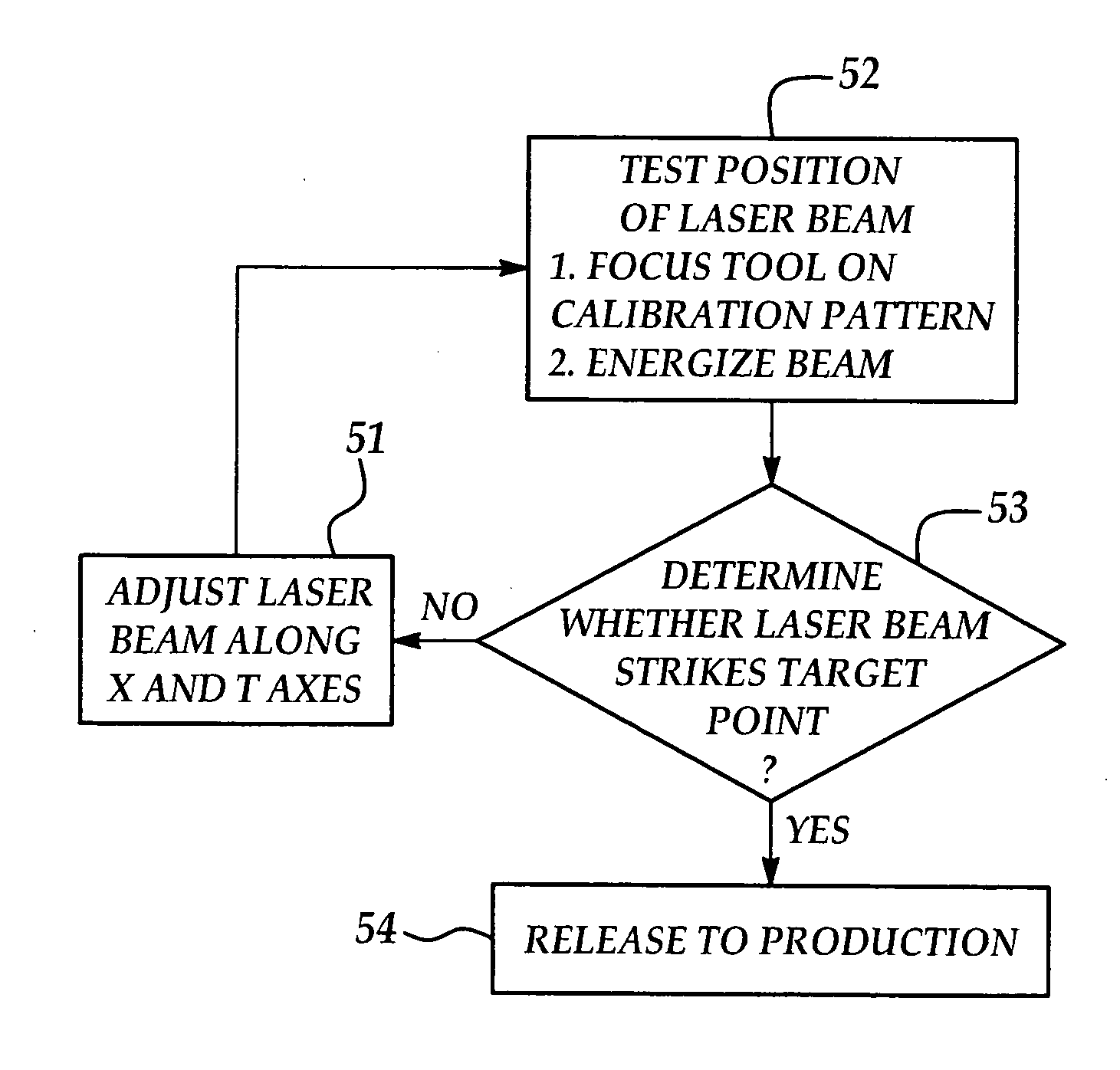
A novel test device and method for calibrating the alignment of a laser beam emitted from a laser metrology tool with respect to a target area on a substrate. The test device includes a laser-sensitive material having a calibration pattern that includes a target point. When the tool is properly adjusted, the laser beam strikes the target point and is released to production. If the laser beam misses the target point, the tool is re-adjusted and re-tested until the laser beam strikes the target point.

Description

FIELD OF THE INVENTION [0001] The present invention relates to high-powered lasers used to measure the thickness and other qualities of metal films on semiconductor wafer substrates in the fabrication of semiconductor integrated circuits. More particularly, the present invention relates to a device and method for calibrating and monitoring the alignment position of a laser beam used to test metal film thickness or other qualities on a wafer substrate. BACKGROUND OF THE INVENTION [0002] In the fabrication of semiconductor integrated circuits, metal conductor lines are used to interconnect the multiple components in device circuits on a semiconductor wafer. A general process used in the deposition of metal conductor line patterns on semiconductor wafers includes deposition of a conducting layer on the silicon wafer substrate; formation of a photoresist or other mask such as titanium oxide or silicon oxide, in the form of the desired metal conductor line pattern, using standard lithogr...

Claims


Application Information

Patent Timeline
IPC IPC(8): G01B11/00
CPCH01L22/34G01B21/042
Inventor CHANG, SHIH-TZUNGLIN, YU-KULIN, SHIH-HOCHEN, KEI-WEIWANG, TING-CHUNSU, CHING-HWANWANG, YING-LANG
Owner TAIWAN SEMICON MFG CO LTD
Learn More