
Diesel engine control system

Active Publication Date: 2006-03-16
DENSO CORP
View PDF5 Cites 15 Cited by
  • Summary
  • Abstract
  • Description
  • Claims
  • Application Information

AI Technical Summary

Benefits of technology

[0013] The present invention addresses the above disadvantages. Thus, it is a first objective of the present invention to provide a diesel engine control system that can limit extinguishment of a former stage injection in an injection type, in which the extinguishment of the former stage injection causes non ignition of latter stage injection. It is a second objective of the present invention to provide a diesel engine control system that can reliably perform pilot flame combustion by pilot flame generative injection without requiring an excessively large quantity of the pilot flame generative injection, which results in deterioration of NOx reducing effect in a retarded combustion operation.

Problems solved by technology

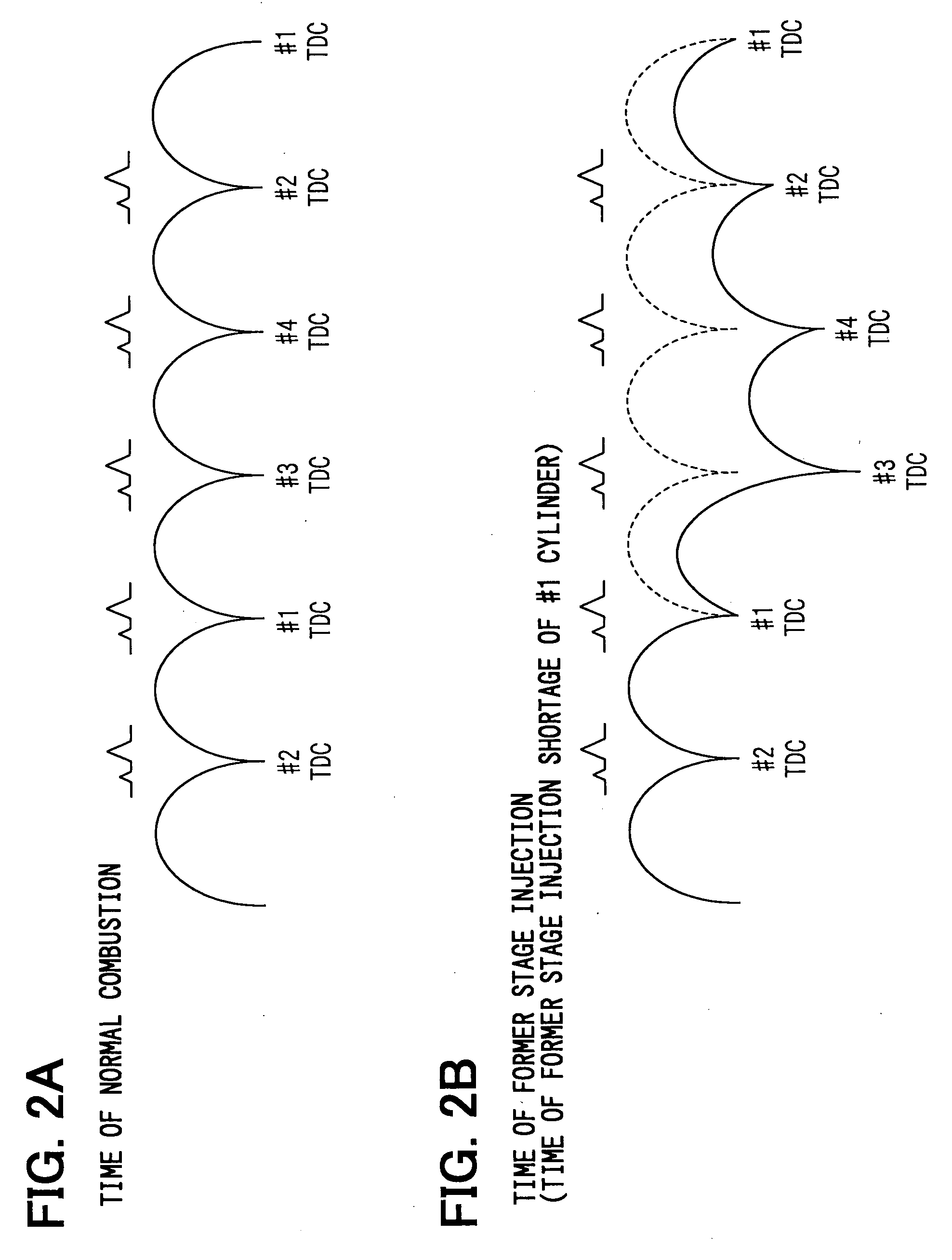
This is due to the fact that when the combustion of fuel of the pilot flame generative injection is extinguished, fuel injected by the large heat generative injection at the latter stage cannot be ignited.
This will likely cause a decrease in the engine torque and / or the engine rotational speed, so that the uncombusted gas may be disadvantageously exhausted from the engine.
This limits use of the retarded combustion operation, in which the above NOx reducing technique is implemented.
However, this will cause a pressure increase and a temperature increase due to the pilot flame combustion.
This will, in turn, cause deterioration of the NOx reducing effect at the time of combusting the large heat generative injection.
As a result, it is not desirable to excessively increase the pilot flame generative injection quantity.

Method used


Image

  • Diesel engine control system
  • Diesel engine control system
  • Diesel engine control system

Examples


first embodiment

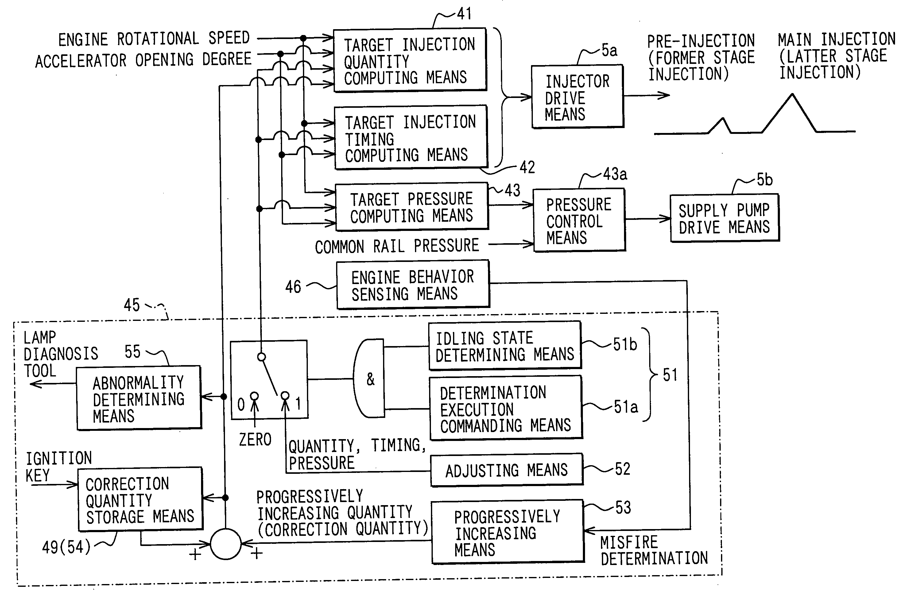
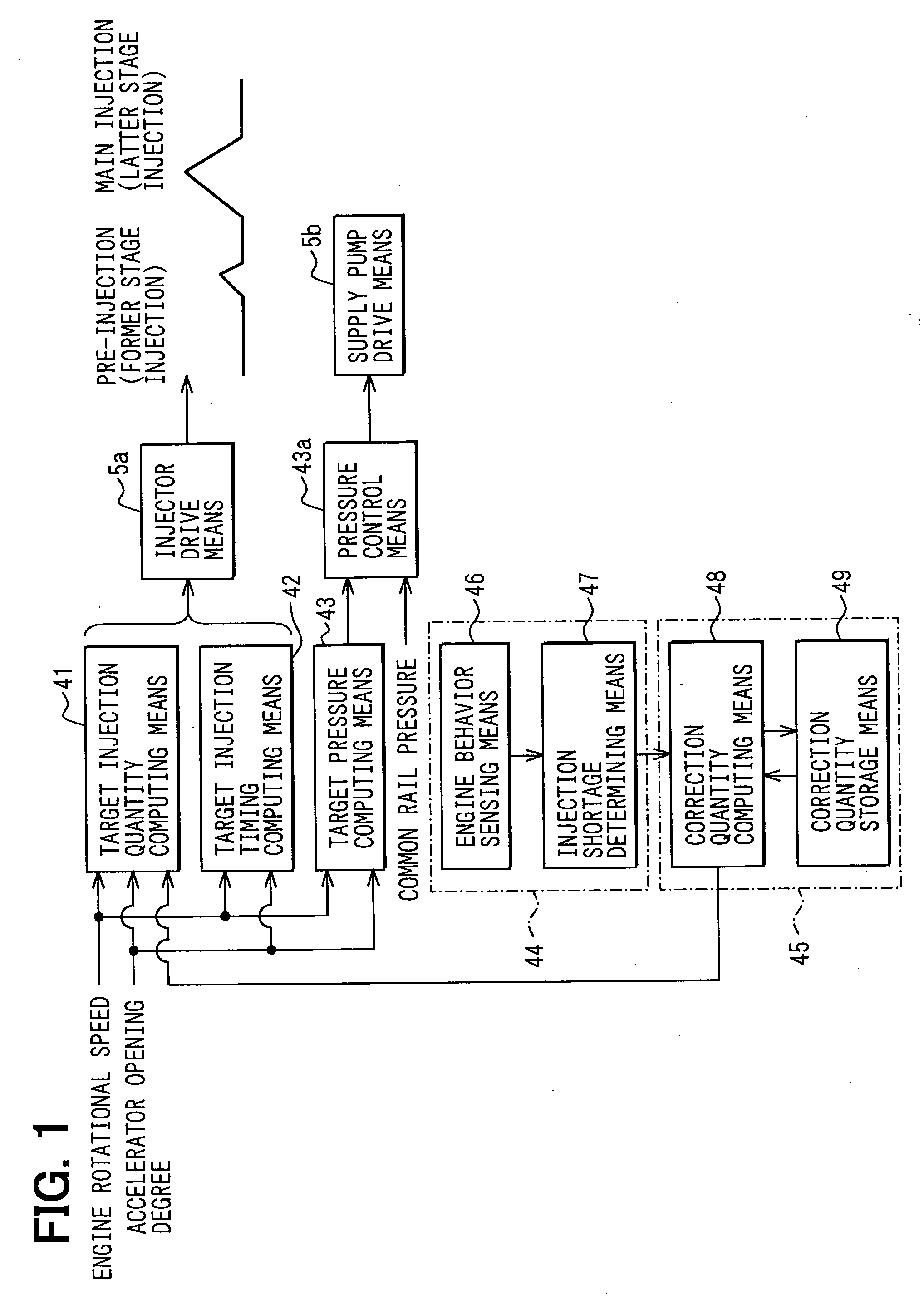
[0030] A first embodiment, in which the present invention is implemented in a common rail type fuel injection system, will be described with reference to FIGS. 1 to 7. A basic structure of the common rail type fuel injection system will be described with reference to FIGS. 6 and 7.

[0031] The common rail type fuel injection system is a system, which injects fuel in, for example, a diesel engine 1. The common rail type fuel injection system includes a common rail 2, injectors 3, a supply pump 4, an ECU 5 (standing for an electric control unit and corresponding to a control device).

[0032] The engine 1 has a plurality of cylinders (cylinders #1-#4 in this particular instance), in each of which an intake stroke, a compression stroke, an expansion stroke and an exhaust stroke are continuously performed. In FIG. 6, although a four cylinder engine is depicted as an example of the engine 1, the engine 1 can be any other type of engine, in which the number of cylinders is other than four.

[...

second embodiment

[0106] In each of the following embodiments, the misfire sensing means 44 (the engine behavior sensing means 46 and the injection shortage determining means 47) is different from that of the first embodiment. Thus, in each of the following embodiments, the misfire sensing means 44 will be described. Furthermore, in each of the following embodiments, functional components, which are similar to those of the first embodiment, are indicated by the same numerals.

[0107] The misfire sensing means 44 of a second embodiment senses the misfire of the engine 1 based on a change in the exhaust gas temperature of the engine 1. Here, an exhaust gas temperature sensor (not shown), which is connected to an exhaust pipe of the engine 1, is used as the engine behavior sensing means 46.

[0108] When the shortage of the pilot flame generative injection occurs, fuel of the large heat generative injection is not combusted, resulting into the misfire. In such a case, the exhaust gas temperature at the tim...

third embodiment

[0111] The misfire sensing means 44 of a third embodiment senses the misfire of the engine 1 based on a change in an air-to-fuel ratio in the exhaust gas of the engine 1. Here, an air-to-fuel ratio sensor (a lambda sensor, such as an oxygen concentration sensor, not diagramatically depicted), which is connected to the exhaust pipe of the engine 1, is used as the engine behavior sensing means 46.

[0112] When the shortage (fuel shortage) of the pilot flame generative injection occurs, fuel of the large heat generative injection is not combusted, resulting into the misfire. In such a case, the oxygen concentration (A / F) at the time of occurrence of the misfire is increased in comparison to the oxygen concentration (A / F) of the other normal cylinders. The injection shortage determining means 47 of the third embodiment is a program, which senses such an increase of the oxygen concentration (A / F) to determine the misfired cylinder.

[0113] The technique for determining the misfired cylinde...


PUM


Abstract

When a learning condition is satisfied, an operational state of an engine is adjusted in a retarded combustion operation to a misfire inducing state, at which misfire is prone to occur in a cylinder of the engine due to shortage of a pilot flame generative injection quantity. When the misfire is sensed, the pilot flame generative injection quantity of the misfired cylinder is progressively increased. Then, when the misfire is eliminated through this, a pilot flame generative correction quantity at the time of eliminating the misfire is stored. Thereafter, the pilot flame generative injection quantity is corrected based on the stored pilot flame generative correction quantity.

Description

CROSS REFERENCE TO RELATED APPLICATION [0001] This application is based on and incorporates herein by reference Japanese Patent Application No. 2004-266752 filed on Sep. 14, 2004. BACKGROUND OF THE INVENTION [0002] 1. Field of the Invention [0003] The present invention relates to a diesel engine control system that can perform a specific injection type, in which latter stage injection is ignited by combustion of former stage injection, and the latter stage injection is not ignited upon extinguishment of the former stage injection. [0004] 2. Description of Related Art [0005] As one type of multi-stage injection operation, there has been proposed a retarded combustion operation. In the proposed retarded combustion operation, fuel injected into a cylinder by pilot flame generative injection (a former stage injection in an injection pattern of the retarded combustion operation) from an injector is compressed and is ignited, and large heat generative injection (a latter stage injection i...

Claims


Application Information

Patent Timeline
IPC IPC(8): F02D41/40
CPCF02D41/08F02D41/1498F02D41/16F02D41/22F02D41/3845Y02T10/44F02D41/403F02D2041/228F02D2200/0602F02D2200/1015F02D2250/31F02D41/402Y02T10/40
Inventor UCHIYAMA, KEN
Owner DENSO CORP
Learn More