Liquid ejecting apparatus

a liquid ejecting and apparatus technology, applied in the direction of printing, other printing apparatus, etc., can solve the problems of image quality suffer, problem not only in ink jet recording apparatuses, but also in other liquid ejecting apparatuses

Inactive Publication Date: 2011-11-10
SEIKO EPSON CORP
View PDF2 Cites 3 Cited by
  • Summary
  • Abstract
  • Description
  • Claims
  • Application Information

AI Technical Summary

Benefits of technology

[0010]An advantage of some aspects of the invention is that it provides a liquid ejecting apparatus capable of adjusting landing positions of a liquid ejected from nozzles onto a landing target even when the distance between the nozzles and the landing target varies.
[0013]In some embodiments, the driving signal is selected for each nozzle group based on the distance between the nozzle and the ejection target and the liquid is ejected based on the corresponding driving signal. Therefore, even when curving or the like occurs in the ejection target and thus the distance between the nozzle and the landing target varies depending on the position in the relative movement direction, the ejection timing is selected so that the liquid lands on the intended position on the ejection target. Accordingly, the variation in the landing position of the liquid on the ejection target is suppressed in each nozzle group. As a consequence, when an image or the like is recorded on the landing target, the image quality is high, thus minimizing deteriorating effects.
[0015]Here, the “ejection mode” refers to various kinds of modes in which the amount of ejected liquid is different depending on usages. Examples of the ejection mode include a mode in which the liquid lands in a range broader than the landing target by increasing the amount of liquid ejected from the nozzle and a predetermined range on the landing target is filled with the liquid more rapidly, and a mode in which the liquid lands on a range narrower than the landing target by reducing the amount of liquid ejected from the nozzle and a more minute image or the like is formed.
[0016]With such a configuration, it is possible to eject the ink at a more appropriate timing in each ejection mode, even when the amount of liquid ejected from the nozzle is different. Thus, the landing position can be more accurate for each ejection mode, thus variations in the landing position are suppressed or minimized.
[0018]With such a configuration, it is possible to eject the liquid at a more appropriate timing, taking into account size of the dot formed on the landing target. Accordingly, it is possible to suppress the variation in the landing position due to the difference in the size of the dot.
[0020]With such a configuration, it is possible to adjust the landing position of the liquid to an appropriate position, even when the speed of the liquid changes.

Problems solved by technology

As a consequence, the image quality suffers.
Moreover, such a problem occurs not only in ink jet recording apparatuses but also other liquid ejecting apparatuses.

Method used


Image

  • Liquid ejecting apparatus
  • Liquid ejecting apparatus
  • Liquid ejecting apparatus

Examples


Embodiment Construction

[0035]Hereinafter, exemplary embodiments of the invention will be described with reference to the accompanying drawings. The embodiments are described below with reference to various specific examples, but the scope of the invention should not be construed as being limited to the embodiments described and illustrated herein unless the description clearly states otherwise. Hereinafter, an ink jet printer will be described as an example of a liquid ejecting apparatus.

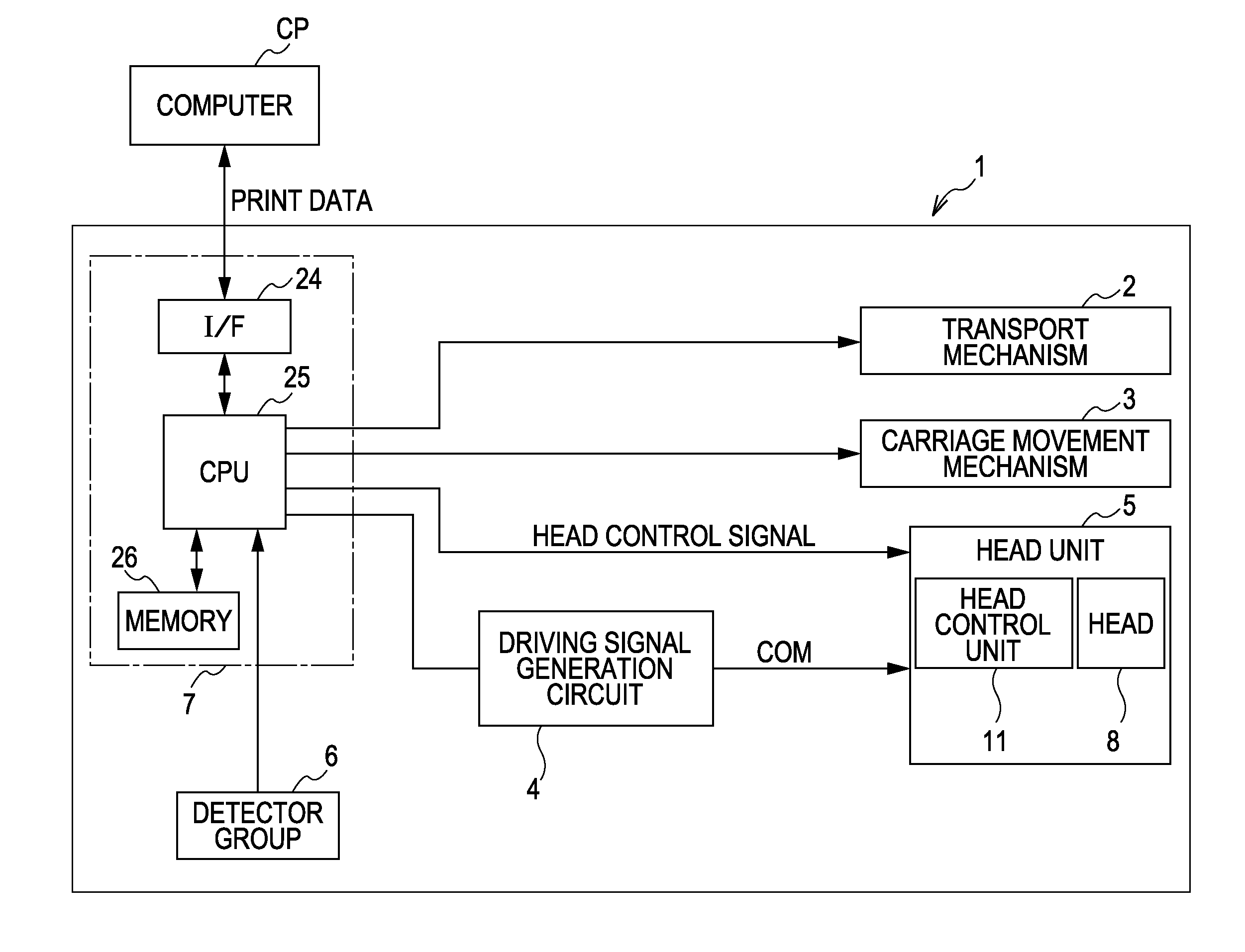
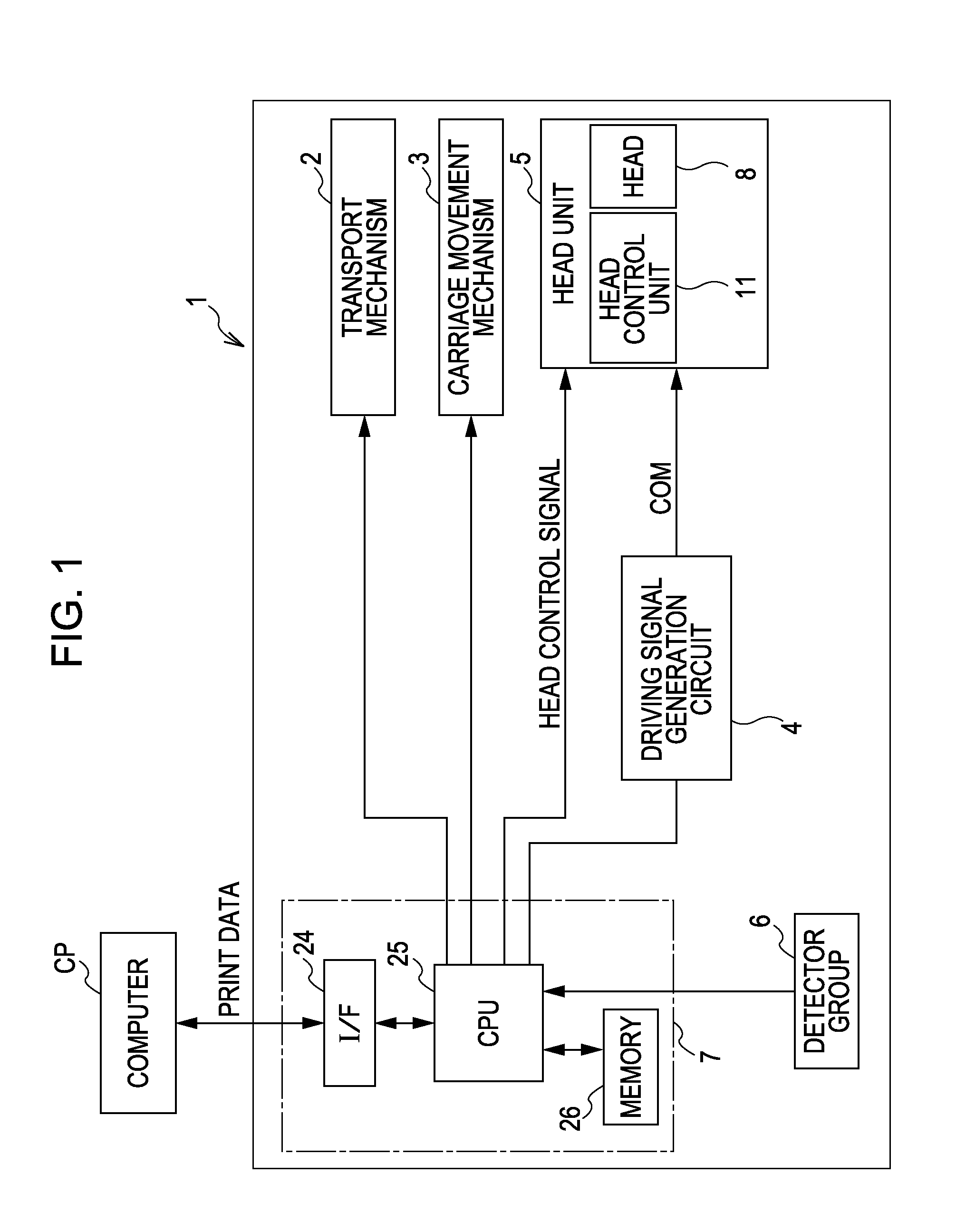
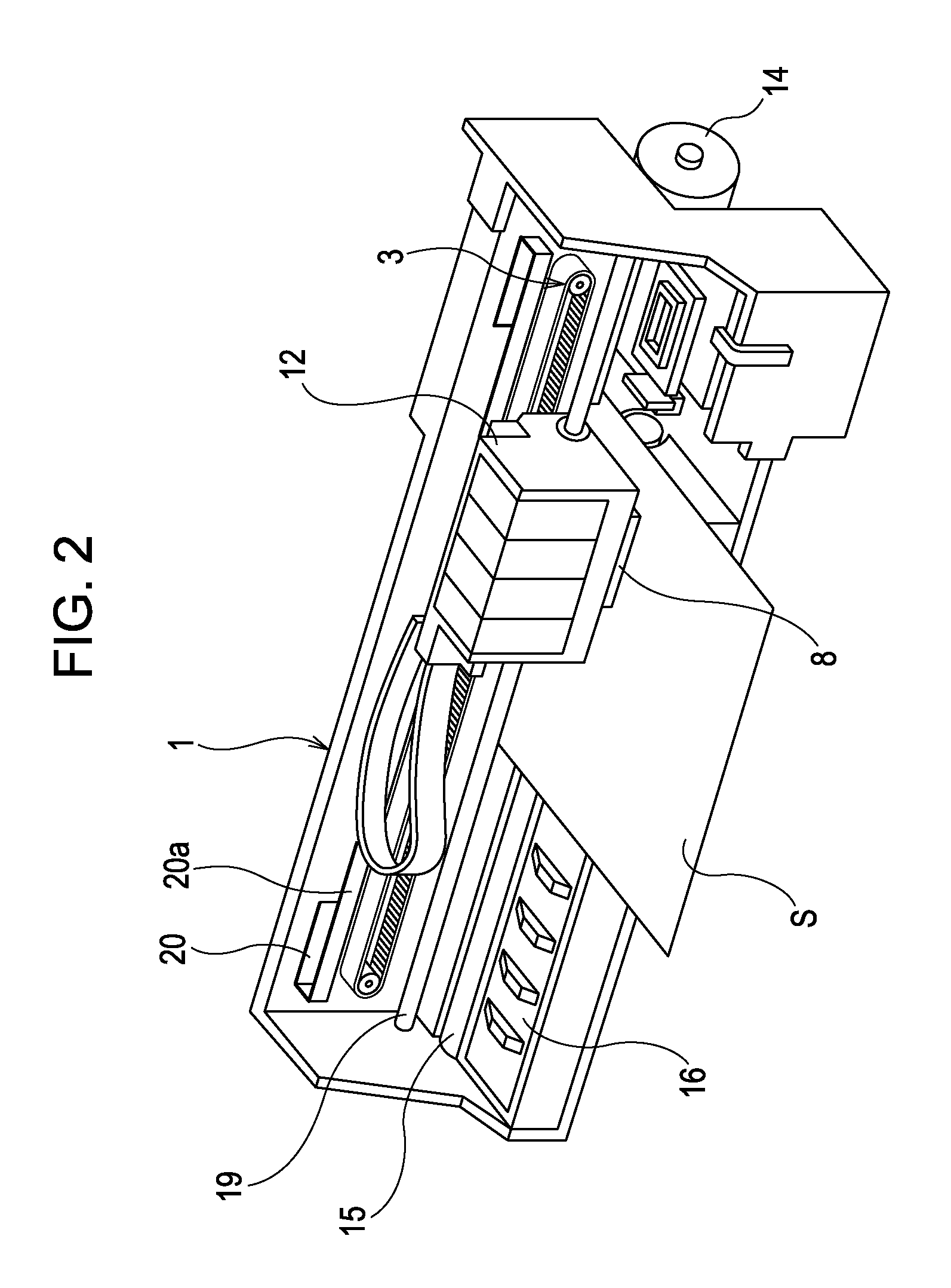
[0036]FIG. 1 is a block diagram illustrating the electric configuration of a printer 1. FIG. 2 is a perspective view illustrating the inner configuration of the printer 1.

[0037]The exemplary printer 1 ejects liquid ink toward a recording medium S such as a recording sheet, a cloth, or a resin film. The recording medium S serves as a landing target for the liquid. A computer CP serving as an external apparatus is connected to the printer 1 so as to be communicable with the printer 1. The computer CP transmits print data of...


PUM


Abstract

A liquid ejecting apparatus includes a liquid ejecting head with a plurality of nozzle groups each having a plurality of nozzles. Each nozzle ejects a liquid onto a landing target by an ejection pulse applied to the liquid. A movement unit relatively moves the liquid ejecting head and the landing target. A control unit sets an ejection timing of the liquid from the nozzles for each nozzle group according to a distance between the nozzles and the landing target. A driving signal generation unit generates driving signals including the ejection pulses, where a timing of each ejection pulse is based on the distance and a speed of the liquid as the liquid crosses the distance. The control unit selects the driving signal for each nozzle group based on the distance and applies a corresponding ejection pulse to the liquid. A liquid ejecting method is also provided.

Description

[0001]This application claims priority to Japanese Patent Application No. 2010-108203, filed May 10, 2010, the entirety of which is incorporated by reference herein.BACKGROUND[0002]1. Technical Field[0003]The present invention relates to a liquid ejecting apparatus such as an ink jet printer, and more particularly, to a liquid ejecting apparatus capable of ejecting liquid to a desired landing position on a landing target.[0004]2. Related Art[0005]A liquid ejecting apparatus is an apparatus which includes a liquid ejecting head that ejects a liquid from nozzles. A representative liquid ejecting apparatus is an image recording apparatus, such as an ink jet printer, which includes an ink jet recording head. Such a printer records an image or the like by ejecting liquid ink onto a recording sheet, from nozzles of the recording head. Liquid ejecting apparatuses are not limited to printers; in recent years various types of manufacturing apparatuses, such as those manufacturing color filte...

Claims


Application Information

Patent Timeline
IPC IPC(8): B41J29/38
CPCB41J2/04573B41J29/38B41J2/04588B41J2/04581
Inventor ISHIKAWA, HIROYUKISUNAGA, YASUO
Owner SEIKO EPSON CORP
Why Eureka
Try Eureka