
Lottery ticket dispenser and ticket bin

a lottery ticket and ticket bin technology, applied in the field of lottery ticket dispenser and ticket bin, can solve the problems of bursting the perforated joints, premature damage of lottery tickets, etc., and achieve the effect of improving the reliability and consistent separation of lottery tickets and optimizing the visibility of the machin

Inactive Publication Date: 2008-12-23
GTECH CORP
View PDF37 Cites 24 Cited by
  • Summary
  • Abstract
  • Description
  • Claims
  • Application Information

AI Technical Summary

Benefits of technology

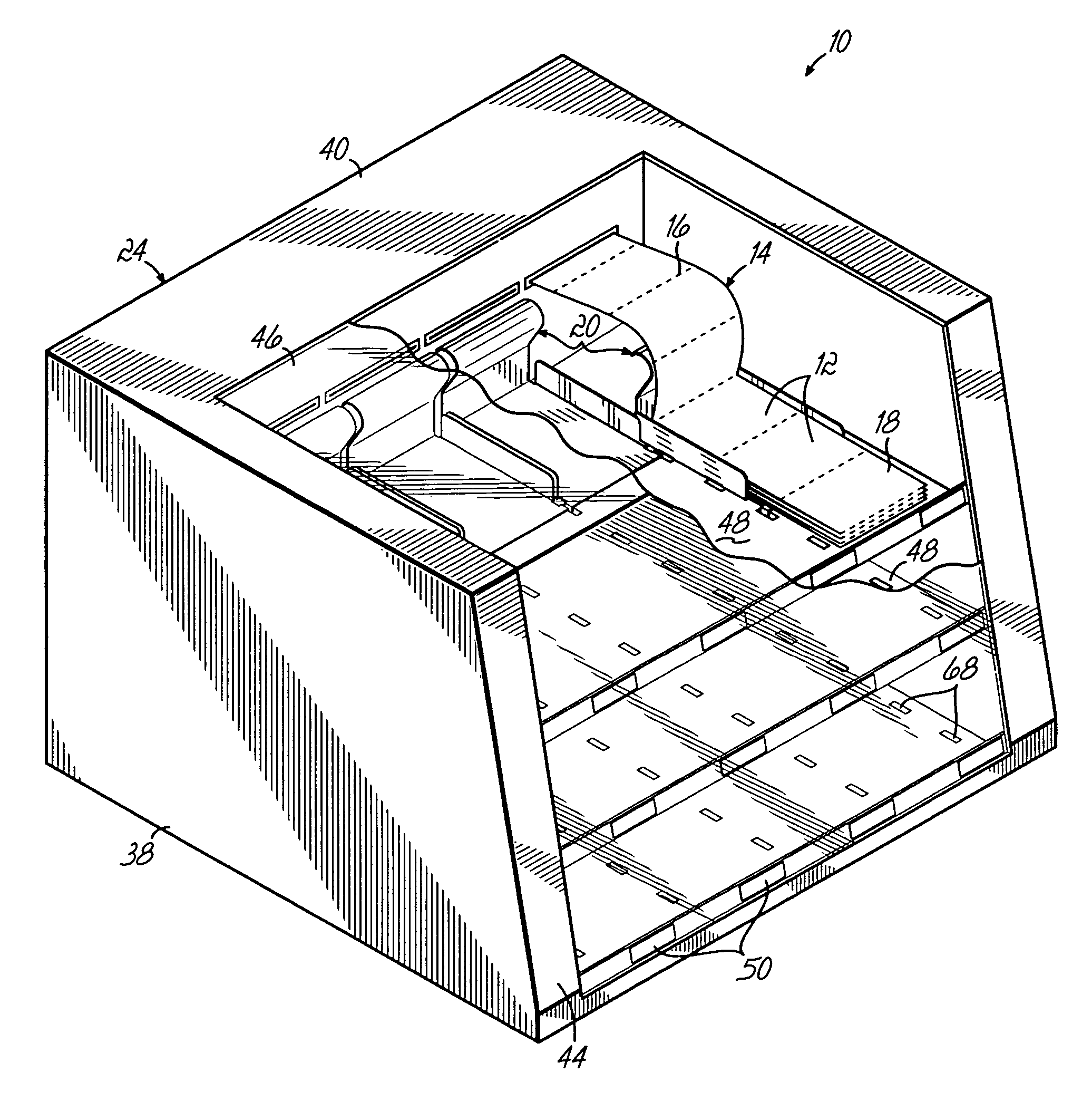
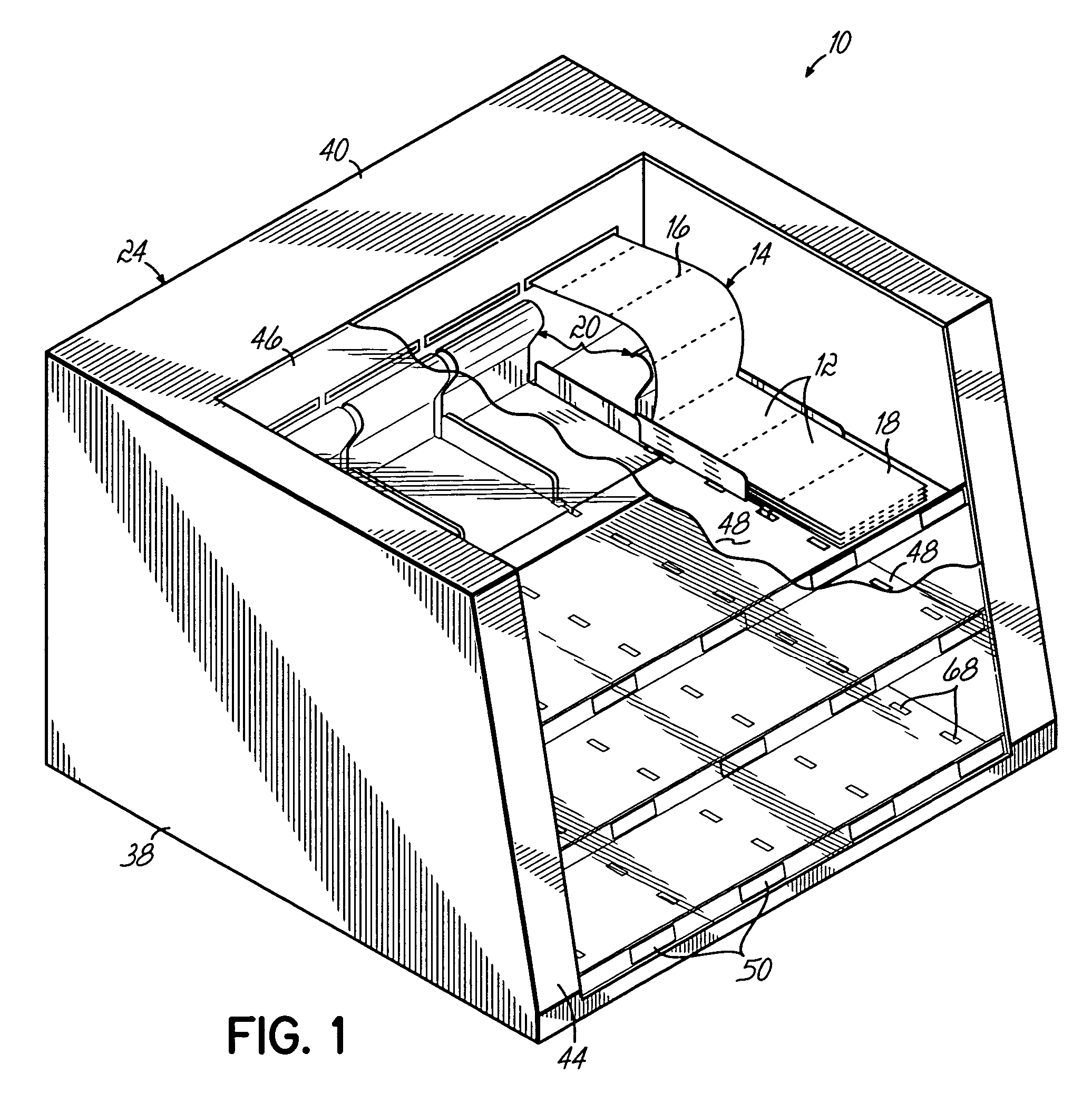
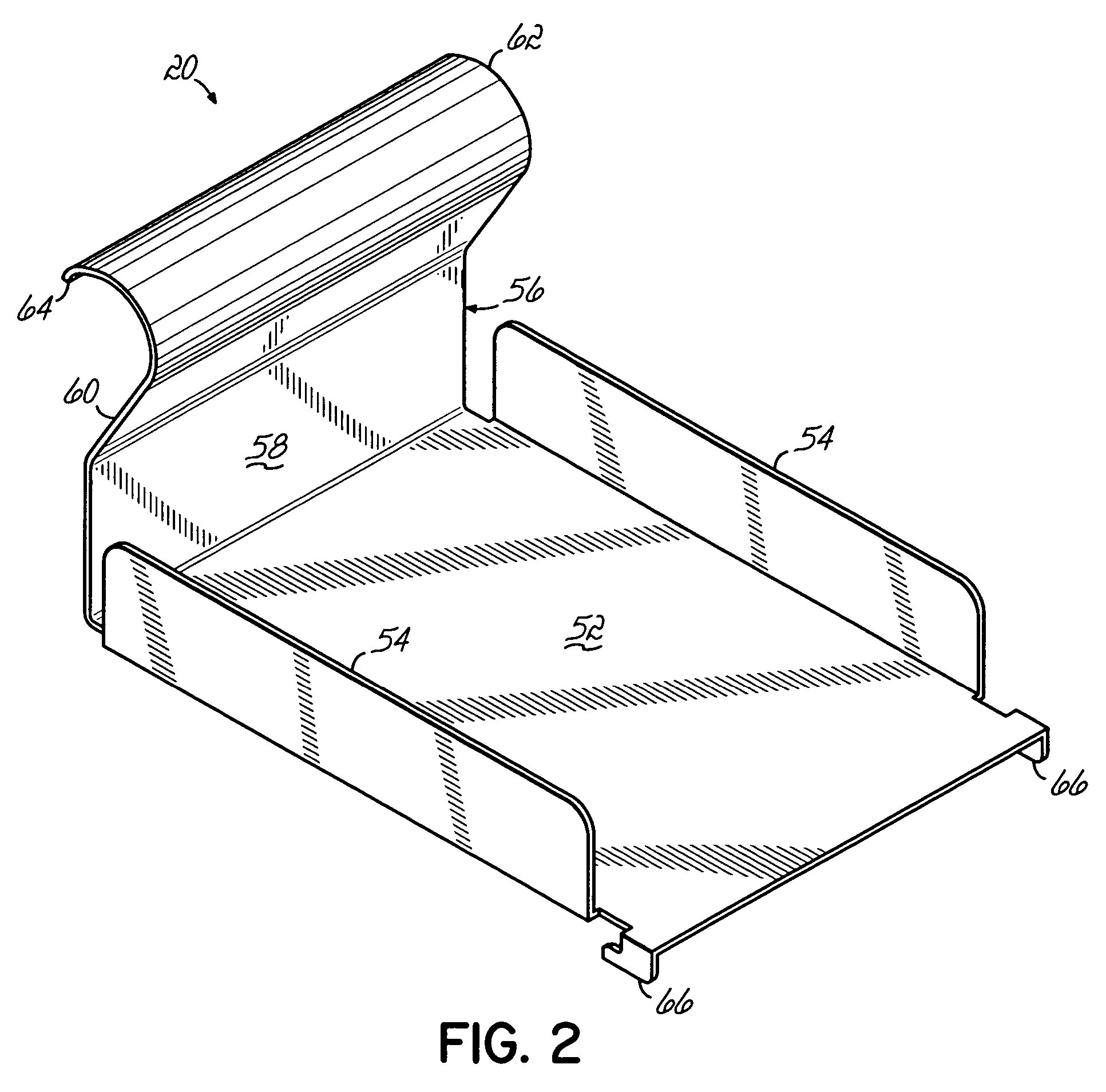
[0012]Advantageously, the ticket bins are adjustably mounted to the associated drawer for proper positioning of a stack of fanfold tickets adjacent to the transparent front panel to provide optimum viewing of the tickets in the housing. In one embodiment, the ticket bin includes a pair of downwardly projecting hooks or tabs which engage a series of sockets in each drawer. The ticket bin therefore can be appropriately be positioned in one of a variety of positions on the drawer depending upon the size and configuration of the stack of fanfold tickets. As such, the tickets can be positioned adjacent the front transparent window regardless of the stack size or configuration by repositioning of the ticket bin on the drawer. The tabs which releasably secure the ticket bins to the drawers are strategically sized, positioned and configured to avoid interference with the adjacent ticket bins and transport of those tickets in the same drawer and superjacent or subjacent drawers.
[0014]As a result of the various features of the invention, an improved lottery ticket dispenser provides a more reliable and consistent separation of lottery tickets while offering optimal visibility in the machine for a wide range of ticket sizes and ticket stack configurations.

Problems solved by technology

Advantageously, excessive stress is not placed on the tickets which in prior art dispensers resulted in prematurely damaging the tickets, partially or completely bursting the perforated joints or the like.

Method used


Image

  • Lottery ticket dispenser and ticket bin
  • Lottery ticket dispenser and ticket bin
  • Lottery ticket dispenser and ticket bin

Examples


Embodiment Construction

[0019]A lottery ticket dispenser 10 according to one embodiment of this invention is shown in FIG. 1. A plurality of individual tickets 12 are connected in a fanfold strip or stream 14. Individual tickets 12 are joined to an adjacent ticket by a line of weakness 16 which typically comprises perforations. The tickets 12 are provided typically by the state authority in a fanfold stack 18 which is compact and easily transportable and typically includes as many as 1,500 tickets in each stack. Each ticket 12 is connected to an adjacent ticket 12 along the line of weakness 16 and it will be understood that each successive following ticket 12 is joined to an adjacent ticket by a similar line of weakness 16.

[0020]Each stack 18 of fanfold tickets 12 are contained in a storage compartment or bin 20 in the lottery ticket dispenser 10. The fanfold stream 14 of tickets 12 is fed along a dispensing path from the ticket bin 20 toward an outlet or dispensing slot 22 in a housing 24 of the dispenser...


PUM


Abstract

A lottery ticket dispenser includes a number of ticket bins mounted in a housing of the dispenser. The ticket bins hold a fanfold stack of tickets proximate a transparent front panel of the dispenser for optimum visibility. The ticket bins are adjustably mounted in the dispenser for proper positioning in one of a variety of positions depending upon the size and configuration of the stack of fanfold tickets. The tickets are transported from the ticket stack upwardly over a guide by a ticket transport mechanism for processing by a powered separator to separate the adjacent tickets apart prior to dispensing. Excessive stress is not placed on the tickets which in prior art dispensers resulted in prematurely bursting the perforated joints apart or damaging the tickets.

Description

BACKGROUND OF THE INVENTION[0001]This invention relates generally to article dispensing systems and more particularly to an improved system and method for dispensing lottery tickets.[0002]State sponsored lotteries are now a popular and accepted method of generating revenue and providing entertainment. One popular form of lottery uses an instant lottery ticket on which winning or non-winning combinations are pre-printed before distribution and the player knows immediately after purchasing the ticket whether or not it is a winning ticket. A common system for distributing these and other types of lottery tickets utilizes ticket dispensing machines located at drug stores, supermarkets, convenience stores and the like. Common concerns associated with such lottery ticket dispensing machines are the speed with which they dispense the tickets, the security or anti-theft characteristics of the dispenser and the ability to accurately and consistently dispense the appropriate number of tickets...

Claims


Application Information

Patent Timeline
Patent Type & Authority Patents(United States)
IPC IPC(8): B26F3/00G07F11/68
CPCG07F11/68Y10T225/30Y10T225/35Y10T225/371Y10T225/10
Inventor WOODS, CURTISENGELHARDT, JR., WILLIAM E.
Owner GTECH CORP
Learn More