Eureka AIR delivers breakthrough ideas for toughest innovation challenges, trusted by R&D personnel around the world.

Robotic machining with a flexible manipulator

Active Publication Date: 2006-03-09
ABB RES LTD
View PDF21 Cites 125 Cited by
  • Summary
  • Abstract
  • Description
  • Claims
  • Application Information

AI Technical Summary

Benefits of technology

[0016] using the signal representative of the force applied by the tool to the w

Problems solved by technology

Today, most of the cleaning operations are performed manually in an extremely noisy, dusty and unhealthy environment.
However, due to the variations and highly irregular shape of the automotive casting parts, solutions based on a CNC machining center usually presented a high cost, difficult-to-change capital investment.
Nevertheless, the foundry industry has not seen many success stories for such applications and installations of industrial robots.
Currently, more than 80% of the application of industrial robots is still limited to the fields of material handling and welding.
The major hurdle preventing the adoption of robots for material removal processes is the fact that the stiffness of today's industrial robot is much lower than that of a standard CNC machine.
Without the capability of realtime force control, the method to eliminate the force effect on the robotic machining process has not been fully addressed in the research community or in industry.
The inherent lower stiffness of the robot has presented many challenges to execute material removal applications successfully.
The first one is the structure deformation and loss of accuracy due to the required machining force.
The contact between the cutting tool and the workpiece generates significant forces.
As a result, a perfect robot program without considering contact and deformation will immediately become flawed as the robot starts to execute the machining task.
Such coupling results in deformation not only in the direction of reaction force and can generate some counter-intuitive results.
Secondly, the lower stiffness also presents a unique disadvantage for machining of casting parts with complex geometry, which means non-uniform cutting depth and width.
As a result, the machining force will vary dramatically, which induces uneven robot deformation.
What this means is that the flatness of the machined plane of the casted part, for example a cylinder head, is so inferior that it renders the robotic process unable to meet the typical tolerance of 0.3˜0.5 mm for a casting cleaning operation.
When machines use carbide tools for roughing operations, the available spindle power is usually the limiting factor on the MRR.

Method used


Image

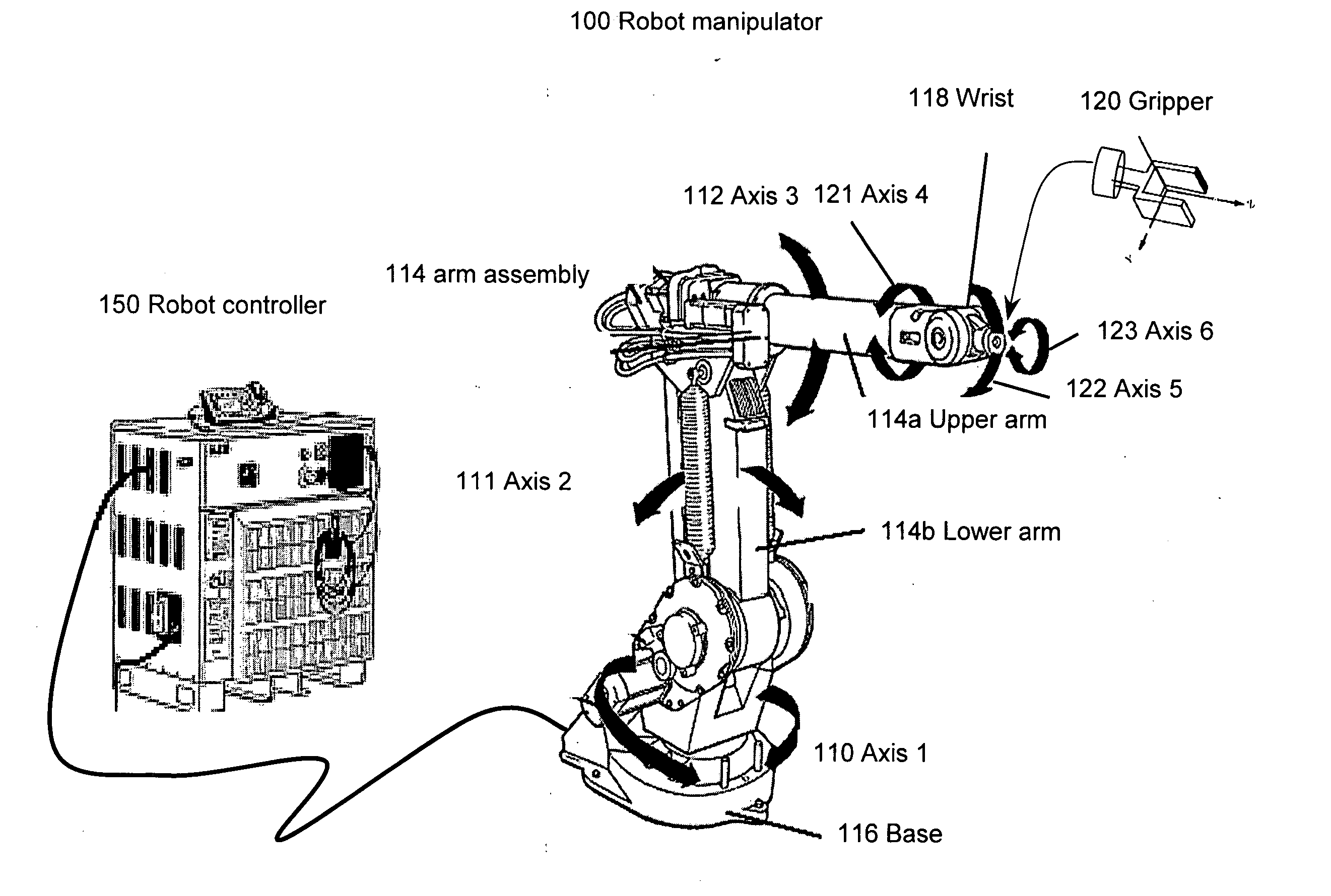
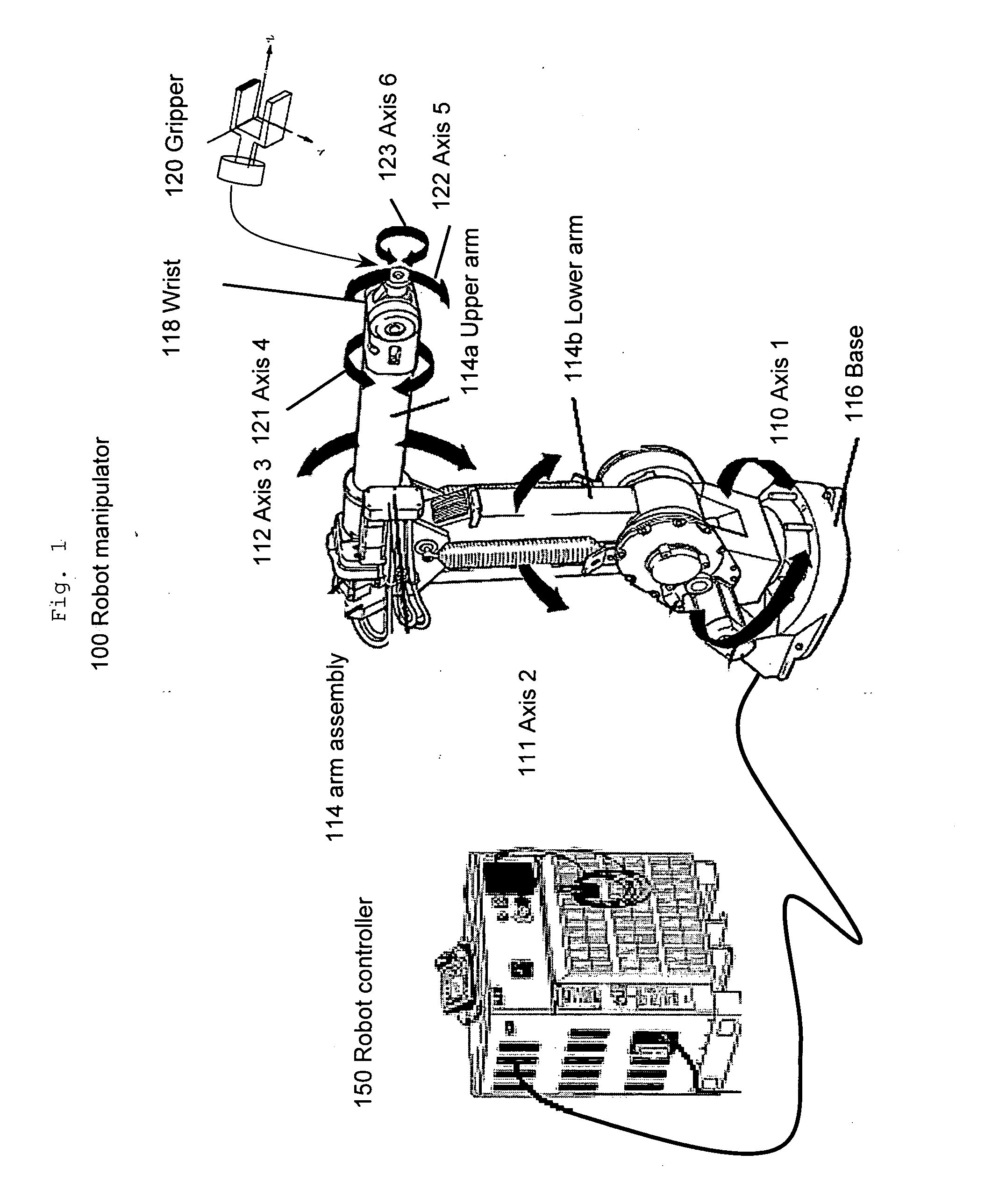
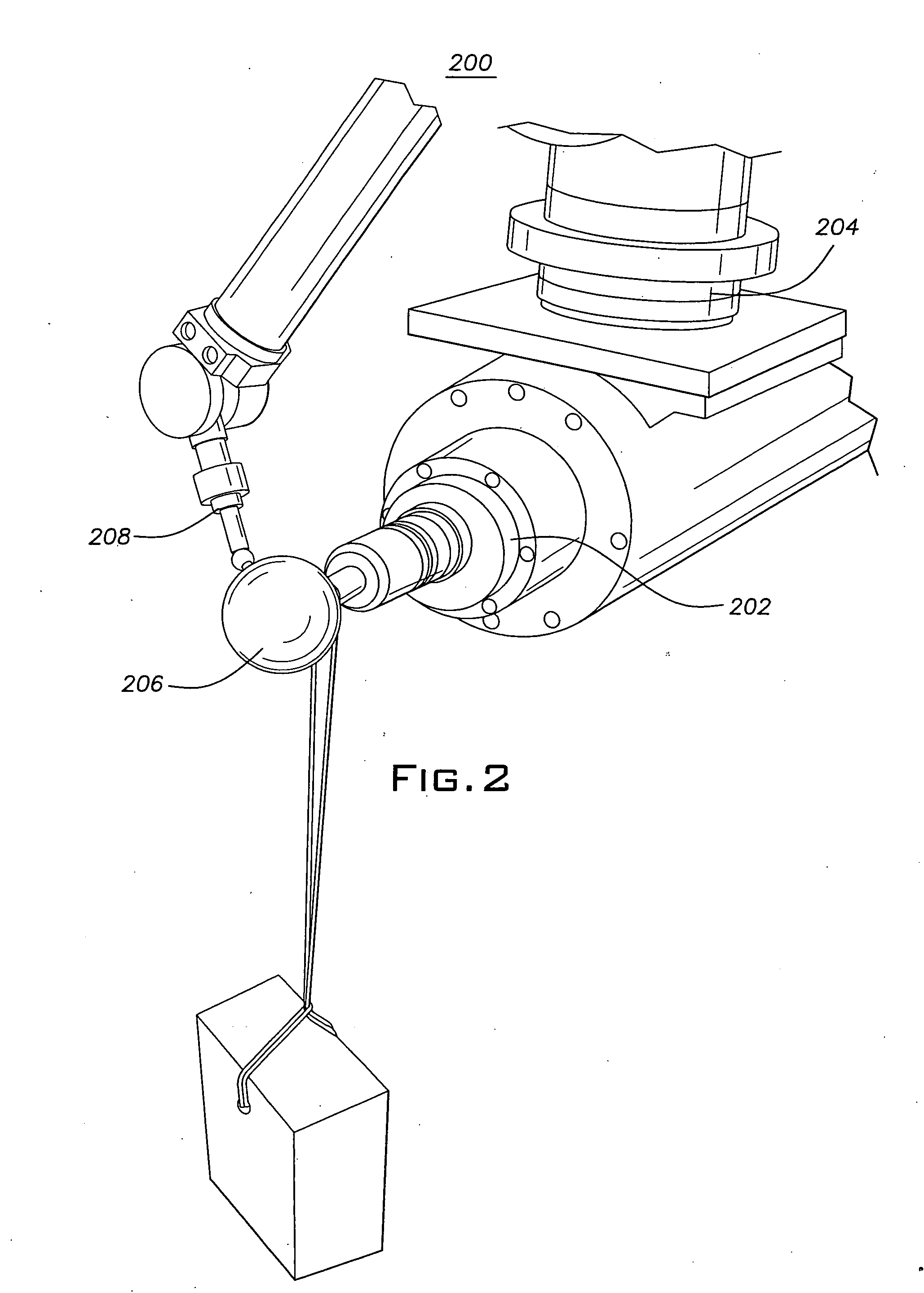
  • Robotic machining with a flexible manipulator
  • Robotic machining with a flexible manipulator
  • Robotic machining with a flexible manipulator

Examples


Embodiment Construction

[0037] As described above, the present invention improves the robotic machining accuracy by reducing machining force induced deformation. While thermal induced error is the largest error component for CNC machining, motion error due to machining force contributes to most of the total machining errors in robots. For example, a 500N cutting force during a milling process will cause a 1 mm position error for a robot instead of a less than 0.01 mm error for a CNC machine. Therefore, in order to achieve higher dimensional accuracy during robotic machining, the deformation due to the interactive force must be compensated.

[0038] Since force measurement and subsequent compensation is carried out in a 3-D Cartesian space, a stiffness model, which relates the force applied at the robot tool tip to the deformation of the tool tip in Cartesian space, is crucial to realize deformation compensation. The model should be accurate enough for the prediction of robot structure deformation under arbit...


PUM

PropertyMeasurementUnit
Forceaaaaaaaaaa

Abstract

A robot machining with a flexible manipulator has an end effector which may either hold the tool to perform the machining or the work piece to be machined. A signal representative of a force applied by said tool to said work piece is used to control either the relative motion between the tool and the work piece to give a controlled material removal rate (CMRR) or the relative position between the tool or the work piece to provide deformation compensation or both CMRR and deformation compensation. A force sensor provides the signal for deformation compensation. For CMRR the signal may be obtained from either a force sensor or the current flowing in the motor of the robot's spindle. The force sensor can be mounted either on the robot or together with either the tool or work piece adjacent to the robot.

Description

CROSS REFERENCE TO RELATED APPLICATION [0001] This application claims the priority of U.S. provisional patent application Ser. No. 60 / 607,939 filed on Sep. 8, 2004, entitled “Machining With Flexible Manipulator: Toward Improving Robotic Machining Performance” the contents of which are relied upon and incorporated herein by reference in their entirety, and the benefit of priority under 35 U.S.C. 119(e) is hereby claimed.FIELD OF THE INVENTION [0002] This invention relates to robots and more particularly to robotic machining. DESCRIPTION OF THE PRIOR ART [0003] The automotive industry represents the fastest-growing market segment of the aluminum industry, due to the increasing usage of aluminum in cars. The drive behind this is not only to reduce the vehicle weight in order to achieve lower fuel consumption and improved vehicle performance, but also the desire for more sustainable transport and the support from new legislation. Cars produced in 1998, for example, contained on average ...

Claims


Application Information

Patent Timeline
IPC IPC(8): B23Q17/00
CPCB23Q17/0966B25J9/1633B25J9/1641G05B19/19G05B2219/37319G05B2219/37355Y10T29/49776G05B2219/45068G05B2219/49079G05B2219/49082G05B2219/49099Y10T29/53039G05B2219/42033
Inventor ZHANG, HUIGAN, ZHONGXUEWANG, JIANJUNZHANG, GEORGE
Owner ABB RES LTD
Why Eureka
Eureka Blog
Learn More