Thin film transistor having an etching protection film and manufacturing method thereof
a technology of protection film and thin film transistor, which is applied in the direction of basic electric elements, electrical equipment, semiconductor devices, etc., can solve the problems of poor machining accuracy and achieve the effect of improving machining accuracy
- Summary
- Abstract
- Description
- Claims
- Application Information
AI Technical Summary
Benefits of technology
Problems solved by technology
Method used
Image
Examples
first embodiment
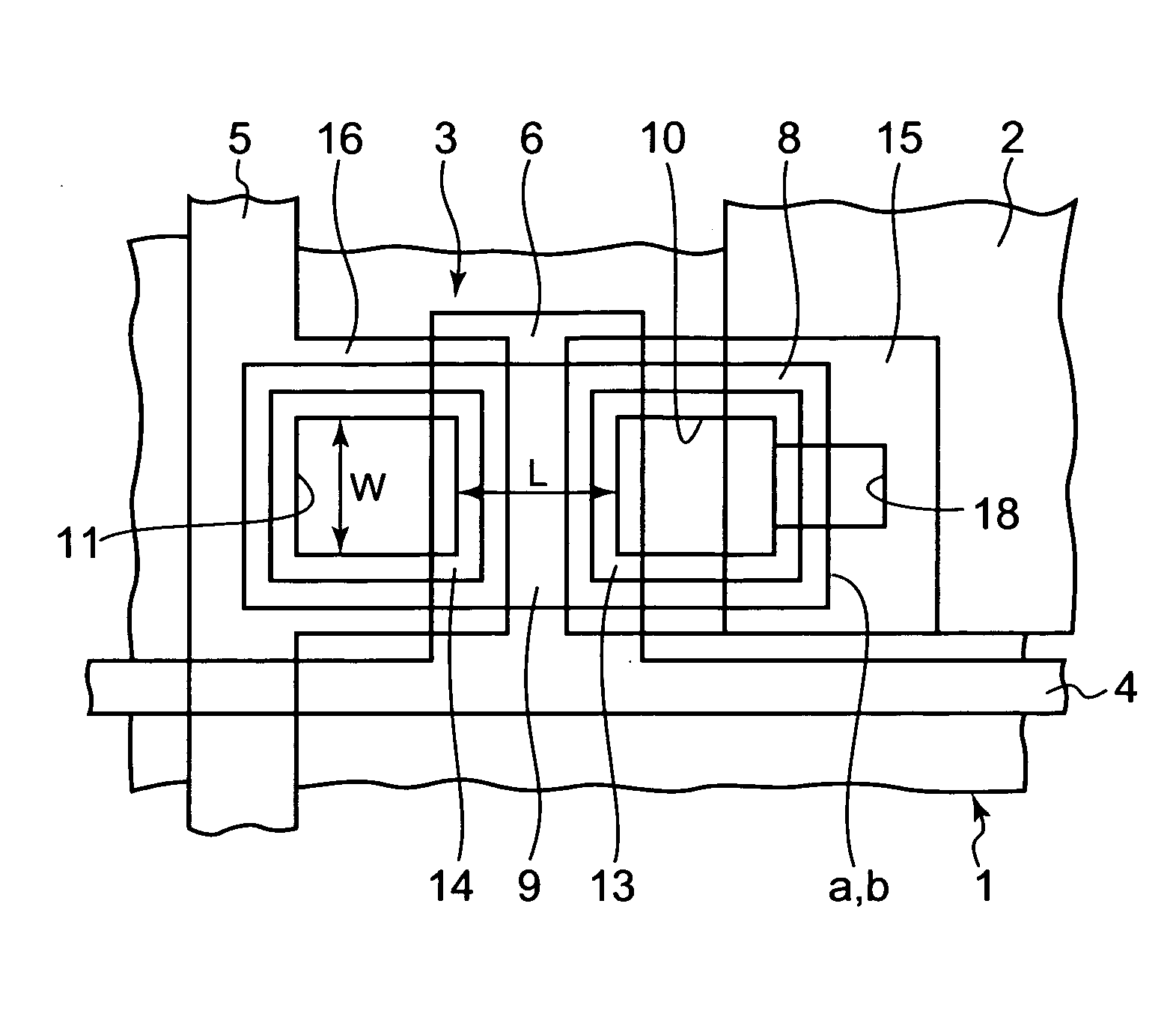
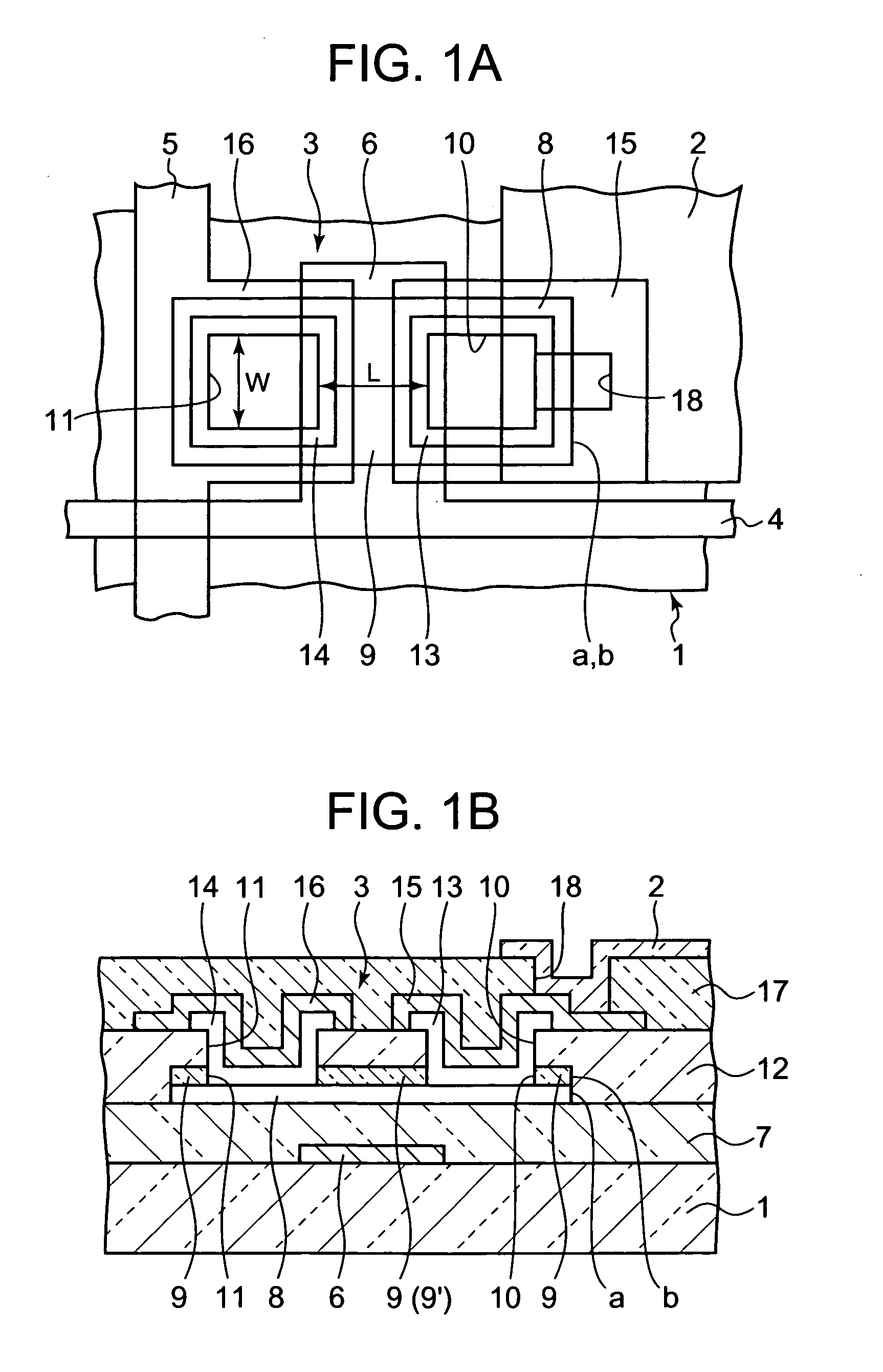
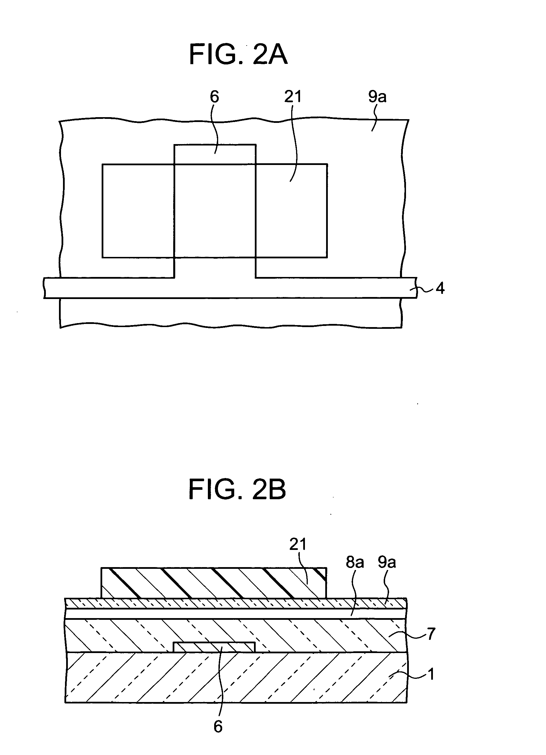
[0059]FIG. 1A is a transparent plan view illustrating a principal part of a liquid crystal display device having a thin film transistor according to a first embodiment of the present invention, and FIG 1B is a cross sectional view cut along a substantially central line in a channel width direction of the thin film transistor illustrated in FIG. 1A. Additionally, in each of FIGS. 2 to 24 explained below, each of 2B to 24B shows a cross sectional view cut along a substantially central line in a channel width direction of the thin film transistor illustrated in each of FIGS. 2A to 24A. The liquid crystal display device includes a glass substrate 1. On the glass substrate 1, there are formed multiple pixel electrodes 2 arranged in matrix, thin film transistors 3 connected to the pixel electrodes 2, respectively, scanning lines 4 arranged in rows to supply a scanning signal to each thin film transistor 3, and data lines 5 arranged in columns to supply a data signal to each thin film tran...
second embodiment
[0090]FIG. 12A is a transparent plan view illustrating a principal part of a liquid crystal display device having a thin film transistor according to a second embodiment of the present invention and FIG. 12B is a cross sectional view cut along a substantially central line in a channel width direction of the thin film transistor illustrated in FIG. 12A. The liquid crystal display device of the present embodiment is different from that illustrated in FIGS. 1A and 1B in the point that no ohmic contact layers 13 and 14 are provided and the source electrode 15 and the drain electrode 16 are directly connected to the semiconductor thin film 8 through the contact holes 10 and 11.
[0091] Thus, in the case of the semiconductor thin film 8 being made of intrinsic zinc oxide, it was recognized that the thin film transistor 3 was normally operated even if the source electrode 15 and the drain electrode 16, which were formed of aluminum, ITO, etc., were directly connected to the semiconductor th...
third embodiment
[0095]FIG. 13A is a transparent plan view illustrating a principal part of a liquid crystal display device having a thin film transistor according to a third embodiment of the present invention, and FIG. 13B is a cross sectional view cut along a substantially central line in a channel width direction of the thin film transistor illustrated in FIG. 13A. The liquid crystal display device of the present embodiment is different from that illustrated in FIGS. 1A and 1B in the point that no upper insulating film 12 is provided. Accordingly, the process for film-forming the upper insulating film 12 can be omitted.
[0096] However, in this case, after the contact hole forming process as illustrated in FIGS. 6A and 6B, when the resist pattern (not shown), which is used in forming the contact holes 10 and 11 on the protection film 9, is stripped using a resist stripper, the peripheral end surface of the semiconductor thin film 8 is exposed to the resist stripper to cause side etching slightly ...
PUM
 Abstract
Description
Claims
Application Information
 - R&D
- Intellectual Property
- Life Sciences
- Materials
- Tech Scout
- Unparalleled Data Quality
- Higher Quality Content
- 60% Fewer Hallucinations
Browse by: Latest US Patents, China's latest patents, Technical Efficacy Thesaurus, Application Domain, Technology Topic, Popular Technical Reports.
© 2025 PatSnap. All rights reserved.Legal|Privacy policy|Modern Slavery Act Transparency Statement|Sitemap|About US| Contact US: help@patsnap.com


