
Magnetic-head apparatus with microactuator having function of short-circuiting both electrodes of epiezoelectric elements and method of manufacturing the same

a microactuator and head technology, applied in the direction of maintaining head carrier alignment, recording information storage, instruments, etc., can solve the problem of large electrical current flowing in the reproducing and recording elements, and achieve the effects of reducing the damage to the reproducing element and the recording element, preventing the accumulation of electrostatic charge, and reducing the damage of the reproducing elemen

Inactive Publication Date: 2006-02-23
TDK CORPARATION
View PDF15 Cites 5 Cited by
  • Summary
  • Abstract
  • Description
  • Claims
  • Application Information

AI Technical Summary

Benefits of technology

[0020] The present invention is aimed at overcoming the above-described problem, and its object is to provide a magnetic head apparatus capable of preventing the accumulation of electrostatic charge and reducing damage to the reproducing element and the recording element by short-circuiting the electrodes of the piezoelectric elements after an inspection of the product magnetic head apparatus, thereby preventing accumulation of electrostatic charges in the piezoelectric element, and thus diminishing the damage of the reproducing and recording elements, as well as a method of manufacturing such a magnetic head apparatus.
[0023] In accordance with the present invention, however, accumulation of electrostatic charges in the piezoelectric elements can be avoided when the magnetic head apparatus is transported or subjected to supersonic cleaning, by virtue of the fact that the potentials of the electrodes of the piezoelectric elements are equalized. It is therefore possible to prevent or suppress the generation of a surge current, thus diminishing the damage of the recording and reproducing elements.
[0024] In the magnetic head apparatus of the present invention, the arrangement may be such that at least one of the electrodes of the piezoelectric elements is a grounding electrode that is connected to a ground, and wherein the wiring member has a control conductive pattern for supplying control signals, the control conductive pattern being connected with electrodes other than the grounding electrode of the piezoelectric elements, and being connected with the ground. Thus, the potentials of all the electrodes of the piezoelectric elements are easily equalized, because these electrodes are all grounded.
[0025] It is preferred that, when a magnetic disk apparatus incorporating the magnetic head apparatus of the present invention has been completed, the control conductive pattern has been disconnected from the ground. It is also preferred that the reliability of the magnetic head apparatus is not adversely affected by the connection and disconnection of the control conductive pattern to and from the ground.

Problems solved by technology

Piezoelectric elements generate very high voltages when subjected to large vibrations during, for example, supersonic cleaning and transportation of the magnetic head apparatus, thus posing a danger of a large electrical current flowing in the reproducing and recording elements.

Method used


Image

  • Magnetic-head apparatus with microactuator having function of short-circuiting both electrodes of epiezoelectric elements and method of manufacturing the same
  • Magnetic-head apparatus with microactuator having function of short-circuiting both electrodes of epiezoelectric elements and method of manufacturing the same
  • Magnetic-head apparatus with microactuator having function of short-circuiting both electrodes of epiezoelectric elements and method of manufacturing the same

Examples


Embodiment Construction

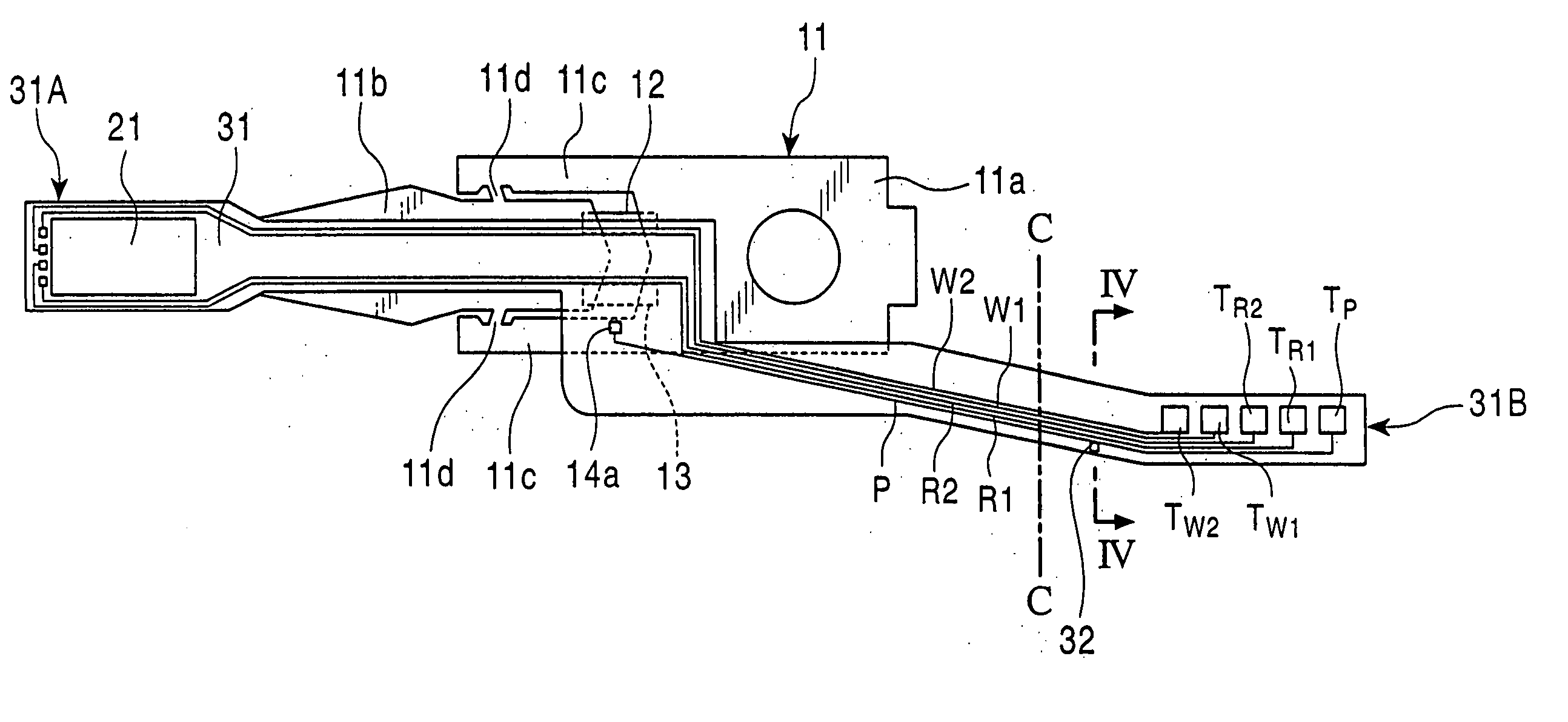
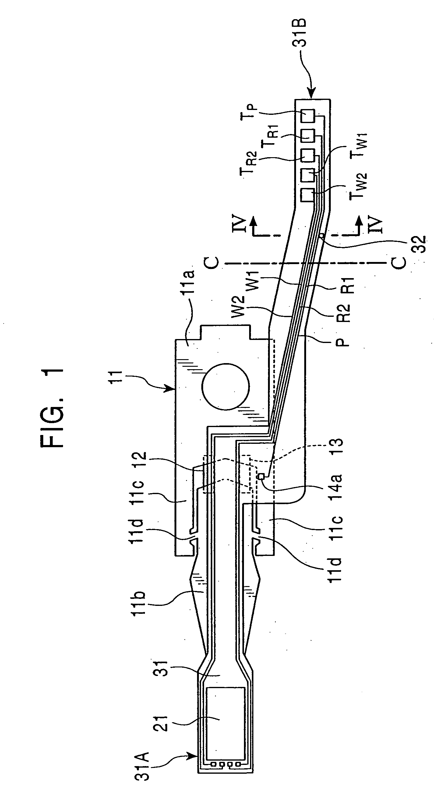
[0048]FIG. 1 is a plan view of the magnetic head apparatus according to the first preferred embodiment of the present invention as seen from the side thereof opposing the recording medium.

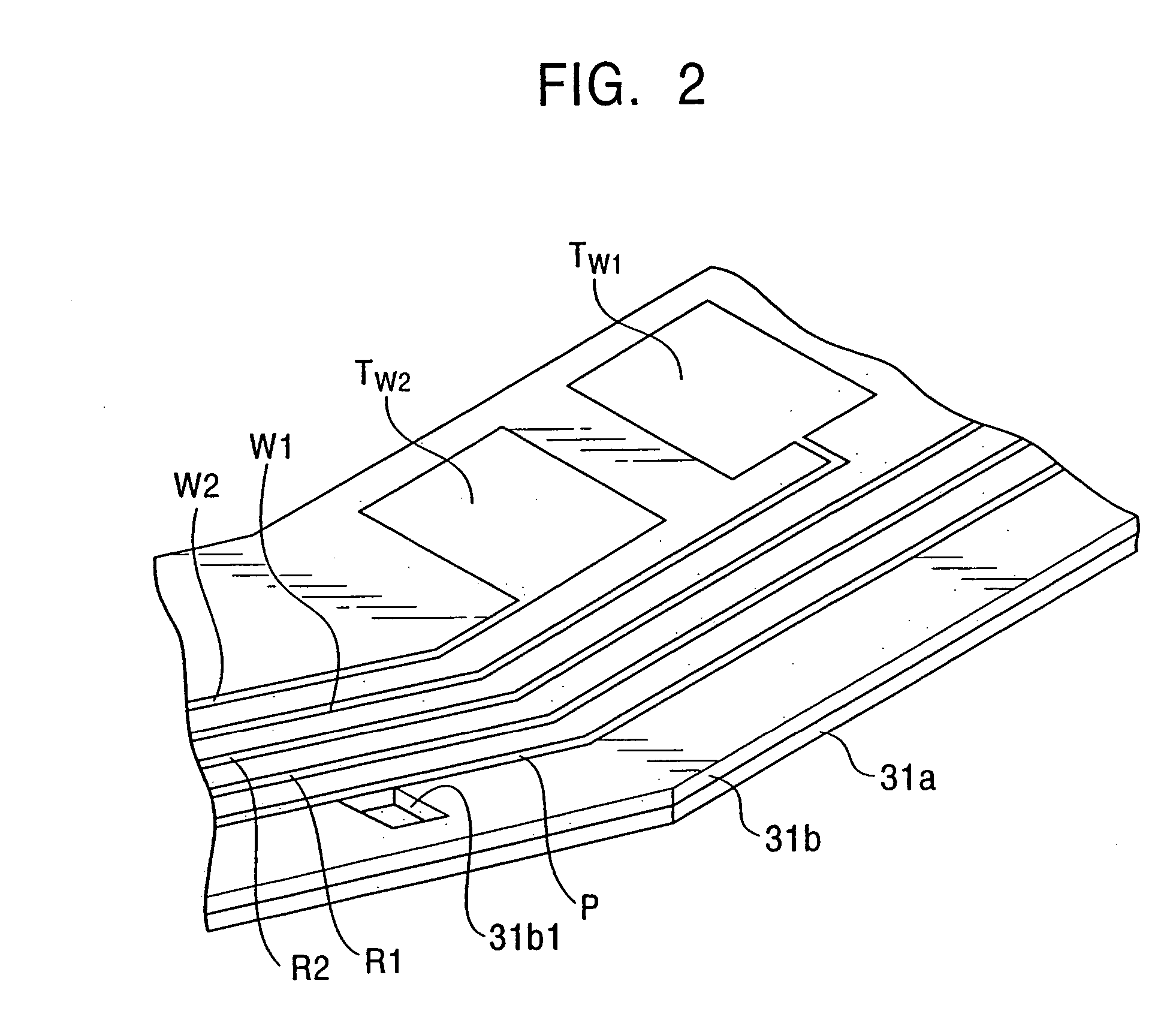
[0049] A wiring member 31 includes reproducing conductive patterns R1 and R2, recording conductive patterns W1 and W2, and a controlling conductive pattern P. These patterns are made of conductive materials such as Cu (copper), and are formed on a thin leaf spring made of a conductive material such as stainless steel, through an intermediary of an insulation layer made of insulating materials such as polyimide.

[0050] A distal end 31A of the wiring member 31 carries a slider 21 provided with a reproducing element for detecting magnetic signals recorded on a recording medium by magnetoresistive effect and a recording element for recording magnetic signals on the recording medium. The distal end 31A of the wiring member 31 has the function of serving as a flexure.

[0051] A wiring member 31, provided...


PUM


Abstract

The supersonic cleaning of a magnetic head apparatus is executed while the control conductive pattern and the conductive leaf spring are electrically connected by means of soldering, and the conductive leaf spring is grounded. This makes it possible to prevent the accumulation of electrostatic charges in the piezoelectric elements on the magnetic head apparatus, thereby preventing the development of surge current or reducing the intensity thereof, and reducing the damage to the reproducing elements and the recording element mounted on the slider of the magnetic head apparatus.

Description

BACKGROUND OF THE INVENTION [0001] 1. Field of the Invention [0002] This invention relates to a magnetic head apparatus comprising a reproducing element with an MR head (reproducing head) mounted thereon, and wherein a piezoelectric element is mounted on a support member supporting the MR head. This invention also relates to a method of manufacturing the magnetic head apparatus. In particular, this invention relates to a magnetic head apparatus that has been improved to avoid damage to the MR head, as well as to a manufacturing method thereof. [0003] 2. Description of the Related Art [0004]FIG. 10 is a top plan view of a conventional hard disk apparatus. A magnetic disk 1 is rotated by a spindle motor [0005] A load beam 4 constituting a support member is connected to the distal end 3a of a rigid carriage 3, and at the distal end 4a of a load beam 4, a slider 5 is fitted through a flexure (not shown). [0006] The load beam 4 comprises a leaf spring. The load beam 4 has a fixed base en...

Claims


Application Information

Patent Timeline
Patent Type & Authority Applications(United States)
IPC IPC(8): G11B5/48G11B5/60G11B5/55G11B5/56G11B5/596G11B21/10G11B21/21
CPCG11B5/4853G11B5/5552Y10T29/49165G11B5/596G11B5/56
Inventor NAKAGAWA, MASAYOSHI
Owner TDK CORPARATION
Learn More