Polygon mirror drive motor

a drive motor and polygon technology, applied in the direction of mirrors, instruments, mountings, etc., can solve the problems of high production cost, difficult to estimate in advance the amount of deformation, and difficult to create the deflective reflection surface, etc., and achieve the effect of high accuracy and image quality of the picture produced on paper

Active Publication Date: 2006-02-23
RAKUTEN GRP INC
View PDF1 Cites 20 Cited by
  • Summary
  • Abstract
  • Description
  • Claims
  • Application Information

AI Technical Summary

Benefits of technology

[0015] According to a polygon mirror drive motor of the present invention, the hexahedron-shape polygon mirror mounted in a rotor portion which rotates in relation to a stator portion has a circular hole having a center point thereof on a rotation axis of the rotor, two square faces that are parallel with each other and orthogonal to the rotation axis, and four mirror facets that are parallel with the rotation axis. In the polygon mirror, when a diameter of the circular center hole and a distance between opposing two of the mirror facets are defined as D and L, respectively, an amo...

Problems solved by technology

However, it is difficult to estimate in advance an amount of the deformation of the deflective reflection surface 101a, and also difficult to create the deflective reflection surface 101a into a concave in accordance with the estimation.
However, since the outside of ...

Method used


Image

  • Polygon mirror drive motor
  • Polygon mirror drive motor
  • Polygon mirror drive motor

Examples


Embodiment Construction

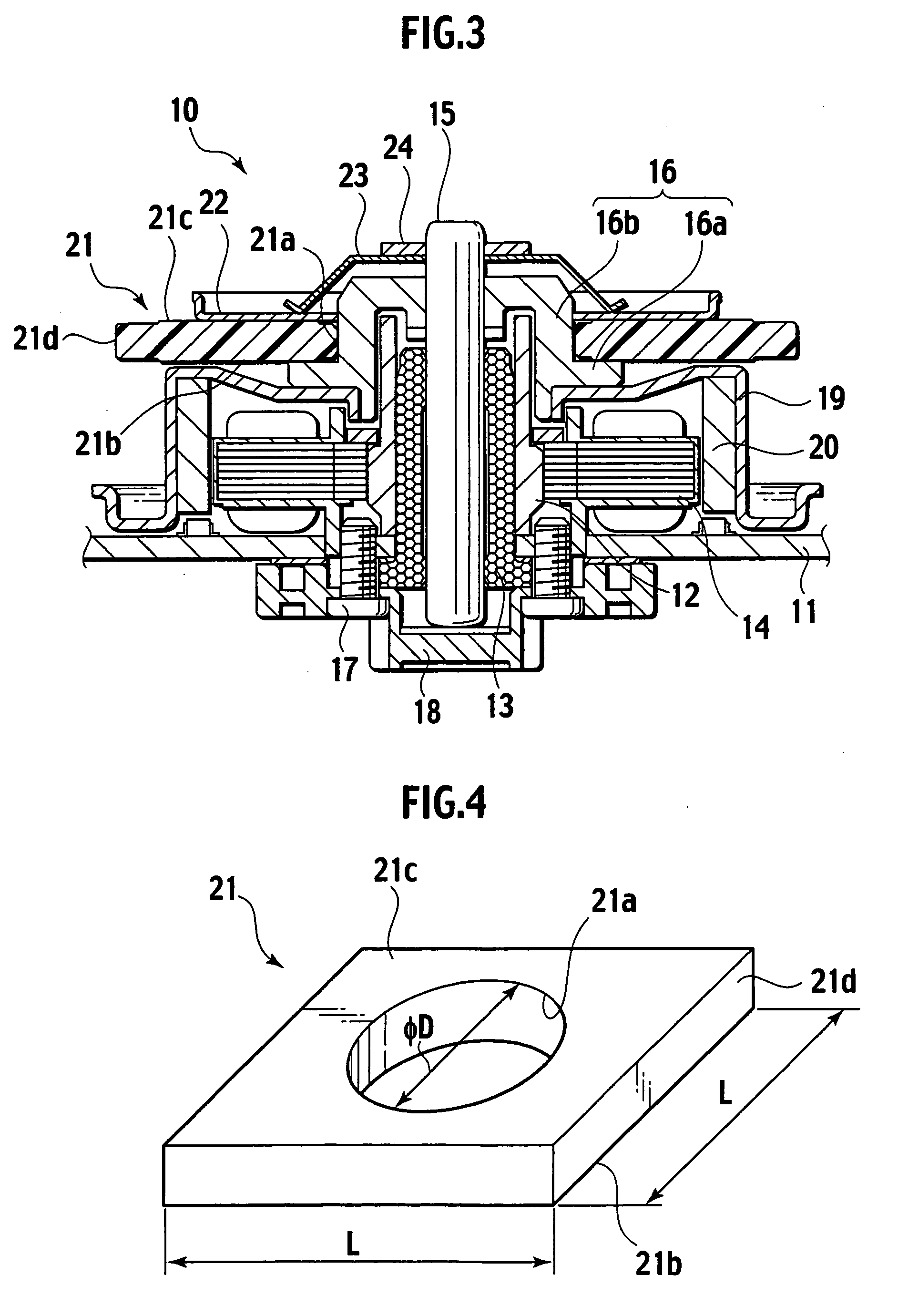
[0027] Referring to FIGS. 3 to 9, a preferred embodiment of the polygon mirror drive motor according to the present invention will be described in detail hereafter.

[0028] As shown in FIG. 3, a polygon mirror drive motor 10 according to the present invention is comprised of a stator portion and a rotor portion.

[0029] In the stator portion, a bearing holder 12 is attached orthogonally on a stator substrate 11 as a base. In addition, an oil-free bearing 13 is fitted into the bearing holder 12, and a plurality of drive coils 14 are arranged at a perimeter of the bearing holder 12.

[0030] In the rotor portion, a rotation shaft 15 is rotatably inserted into the oil-free bearing 13 fitted in the bearing holder 12. A flange member 16 is pushed into the upper end of the rotation shaft 15 and the lower end of the rotation shaft 15 was supported by a holder member 18 that is attached on the back surface of the stator substrate 11 with the aid of a screw 17.

[0031] The flange member 16, which...


PUM


Abstract

A polygon mirror drive motor according to the present invention comprises a stator and a rotor having a hexahedron-shaped polygon mirror and a rotation drive shaft. The polygon mirror in one preferred mode is comprised of two square faces that are parallel with each other and orthogonal to said rotation drive shaft, the two square faces having each a center hole in which said rotation drive shaft is inserted, and four mirror facets that are parallel with said rotation drive shaft. In the polygon mirror, a value of D/L is preferably in a range of from 0.37 to 0.41 where D is a diameter of said center hole and L is an edge length of said two square faces.

Description

BACKGROUND OF THE INVENTION [0001] 1. Field of the Invention [0002] The present invention relates to a polygon mirror drive motor for use in a laser beam printer, a photocopier or the like, and is equipped with a polygon mirror for deflecting and scanning a laser beam. [0003] 2. Description of the Related Art [0004] In a laser beam printer or a photocopier is utilized a polygon mirror drive motor. In the polygon mirror drive motor, a polygon mirror configured by combining a plurality of mirror facets into a polygonal shape, seen in plain view, is mounted in a rotor portion that rotates with respect to a stator. With this, the polygon mirror can rotate at high speed to deflect and scan a laser beam being incident upon the plurality of the mirror facets. A scanning light beam produced by deflecting and scanning the laser beam with the polygon mirror creates an image on a photoreceptor or paper. [0005] By the way, since a polygon mirror that is produced with a plurality of mirror facet...

Claims


Application Information

Patent Timeline
IPC IPC(8): G02B26/08G02B5/08G02B7/182
CPCG02B26/121
Inventor MORI, SHIGEYOSHI
Owner RAKUTEN GRP INC
Why Eureka
Try Eureka