
Engine mount system

a technology of engine mount and engine, which is applied in the direction of machine supports, mechanical equipment, shock absorbers, etc., can solve the problems of inability to achieve the effect of efficient suppression of engine vibration, inability to achieve engine vibration suppression efficiency, and inability to achieve engine vibration suppression effect, etc., to achieve the effect of reducing vehicle sound level and increasing the number of different mount characteristics

Inactive Publication Date: 2006-02-23
HONDA MOTOR CO LTD
View PDF6 Cites 11 Cited by
  • Summary
  • Abstract
  • Description
  • Claims
  • Application Information

AI Technical Summary

Benefits of technology

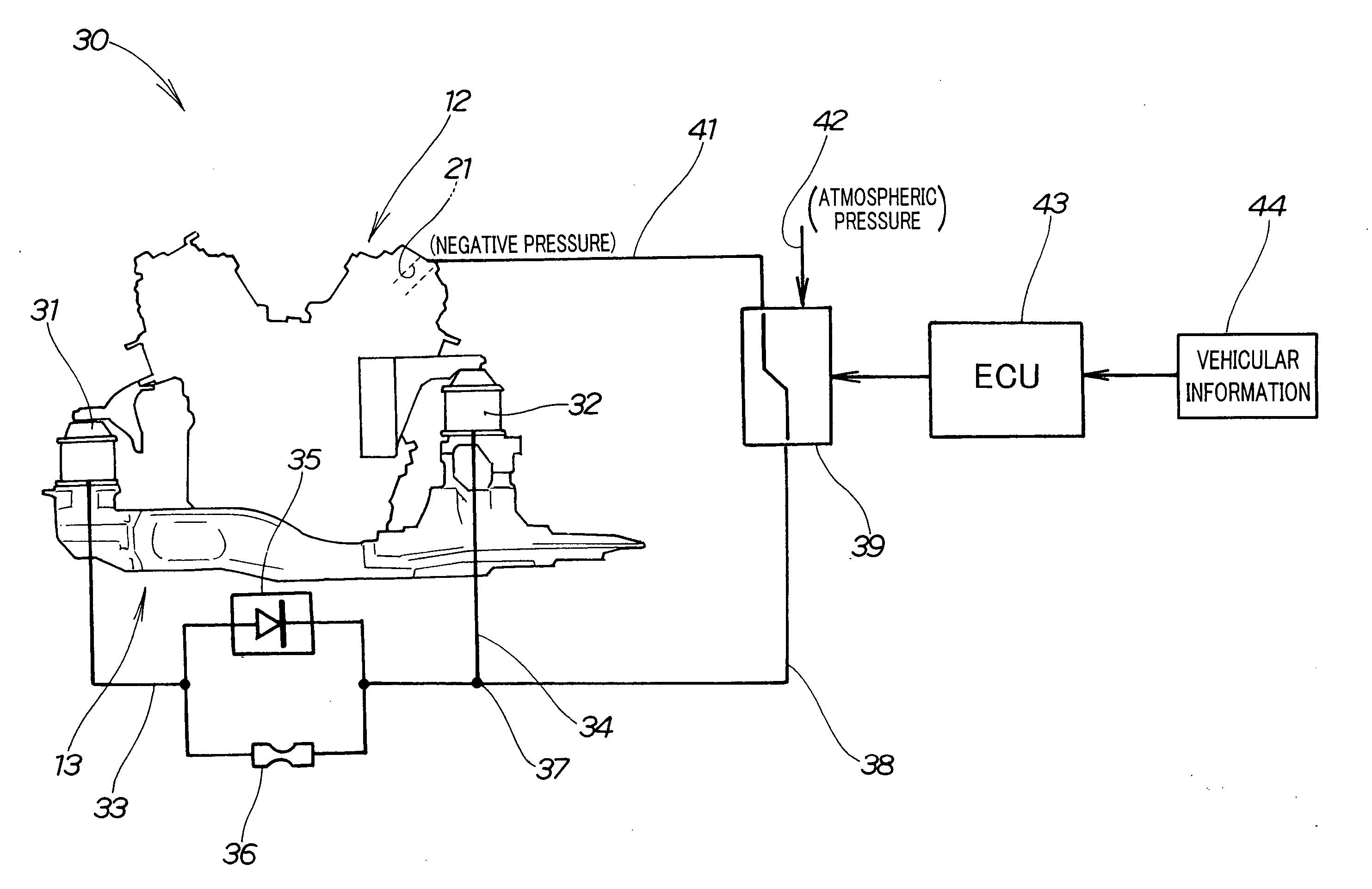
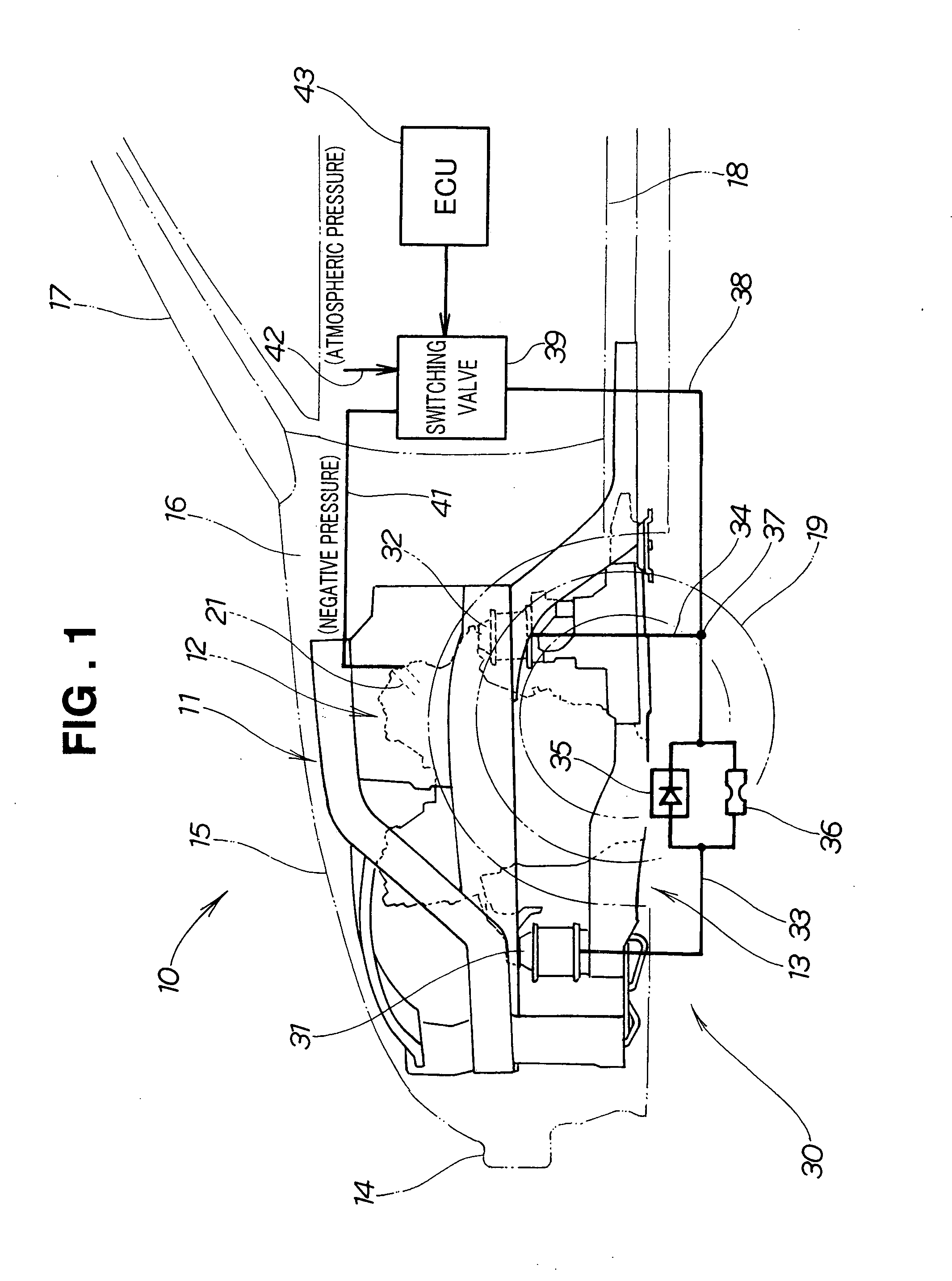
[0010] In the present invention, the check valve and the orifice portion for restricting the flow rate of the fluid flowing therethrough are provided in parallel on the one of the pipelines. With this arrangement, flows of fluids into the engine mounts are controlled such that switching of the pressure in one engine mount from the negative pressure to the atmospheric pressure or from the atmospheric pressure to the negative pressure occurs at different timing than switching of the pressure in another engine mount. Thus, the engine mount system can provide another mode different from the other two modes in which the negative pressure is introduced in the respective engine mounts and in which the atmospheric pressure is introduced in the respective engine mounts. By thus providing the third damping mode, the engine mount system can efficiently absorb the engine vibrations and improve a sound level of the vehicle.
[0012] Thus, only a single switching valve is required to switch the pressure in two of the system engine mounts. This results in a reduced cost of the vehicle.
[0014] In the engine mount system of the present invention, the pressure in the respective switchable liquid-filled engine mounts is switched to the negative or atmospheric pressure by the associated switching valves. Thus, by combining switching patterns of the respective switching valves, it is possible for the engine mounts to provide an increased number of different mount characteristics. The engine mount system can provide a particular type of mount characteristics well matched with a vehicular state having an engine speed other than an idle speed and a high speed. This contributes to further reduction of the vehicle sound level.

Problems solved by technology

However, the engine mount system 300 is less suitable for this purpose because all the mount characteristics of the plural engine mounts 302 are changed or switched simultaneously.
As a result, efficient suppression of vibrations from the engine 301 can not be achieved.
As a result, inappropriate mount characteristics not corresponding to the speed of the engine would be inevitably used.

Method used


Image

  • Engine mount system
  • Engine mount system
  • Engine mount system

Examples


first embodiment

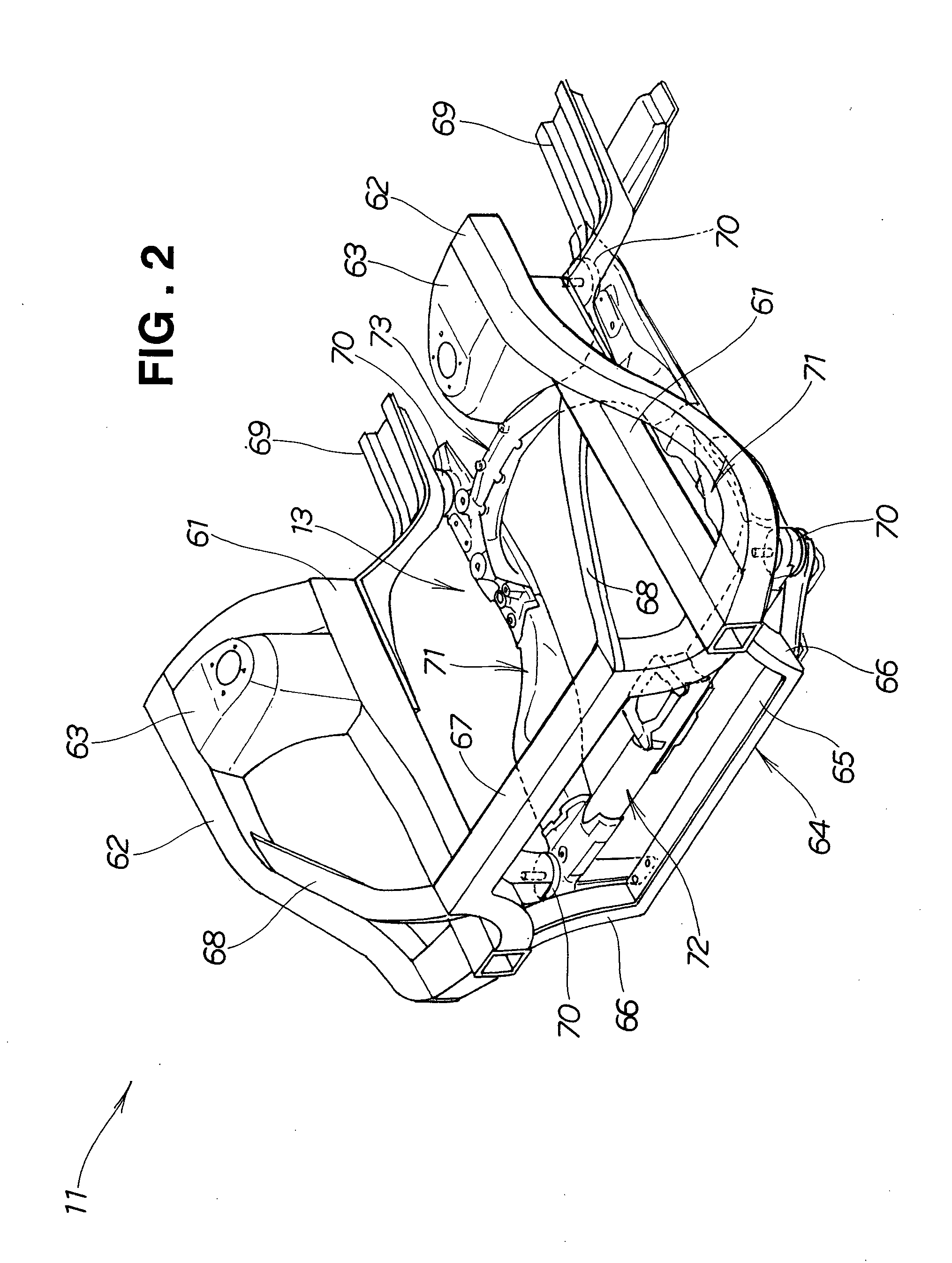
[0030] An engine mount system 30 according to the present invention includes two vacuum-driven switchable liquid-filled mounts 31, 32 that are switchable to provide different vibration damping characteristics by selectively introducing negative pressure or atmospheric pressure, and the engine 12 supported by the engine mounts 31, 32 on the vehicle body frame 11.

[0031] The vacuum-driven switchable liquid-filled mount 31 is hereinafter referred to as “first engine mount 31”. Similarly, the vacuum-driven switchable liquid-filled mount 32 is hereinafter referred to as “a second engine mount 32”.

[0032] To the first engine mount 31, there is provided a first pipeline 33 for introducing a negative or atmospheric pressure into the engine mount 31. To the second engine mount 32, there is provided a second pipeline 34 for introducing a negative or atmospheric pressure into the engine mount 32.

[0033] One of the first pipeline 33 and the second pipeline 34, namely the first pipeline 33 is pro...

second embodiment

[0064] As shown in FIG. 7, the engine mount system 130 according to the present invention includes first and second switching valves 45, 46 provided on the first and second pipelines 33, 34, respectively, for switching pressure in the first and second engine mounts 31, 32 to negative or atmospheric pressure.

[0065]FIG. 8 shows an arrangement of the engine mount system 130 according to the second embodiment of the present invention.

[0066] The engine mount system 130 includes the first engine mount 31 supporting the front part of the engine 12, the second engine mount 32 supporting the rear part of the engine 12, the first pipeline 33 connected to the first engine mount 31, the first switching valve (first solenoid valve) 45 connected to the first pipeline 33, the second pipeline 34 connected to the second engine mount 32, the second switching valve (second solenoid valve) 46 connected to the second pipeline 34, a first negative pressure introducing pipe 47 connected to the first swit...


PUM


Abstract

An engine mount system includes multiple liquid-filled engine mounts switchable to provide different mount characteristics by selectively introducing negative pressure or atmospheric pressure. On one of pipelines connected to the respective engine mounts for introducing the negative or atmospheric pressure into the respective engine mounts, a check valve and an orifice portion are provided in parallel. The orifice portion restricts an amount of air flowing therethrough, so that the mount characteristic of the engine mount connected to the one pipeline equipped with the check valve and the orifice portion does not undergo an abrupt change when the pressure introduced in the engine mount is switched from the negative pressure to the atmospheric pressure.

Description

CROSS-REFERENCE TO RELATED APPLICATIONS [0001] The present invention claims priority under 35 USC 119 based on Japanese patent application Nos. 2004-232621 and 2004-232623, both filed Aug. 9, 2004. The entire disclosures of these Japanese patent applications are incorporated herein by reference. FIELD OF THE INVENTION [0002] The present invention relates to an engine mount system using vacuum-driven switchable liquid-filled engine mounts that are switchable to provide different vibration damping characteristics by selectively introducing negative pressure or atmospheric pressure. BACKGROUND OF THE INVENTION [0003] Engine mount systems using vacuum-driven switchable liquid-filled engine mounts are in practical use. The liquid-filled engine mounts are switchable to provide different vibration damping characteristics by selectively introducing negative pressure from the intake manifold of an engine or atmospheric pressure. By thus switching the pressure introduced therein, the engine m...

Claims


Application Information

Patent Timeline
IPC IPC(8): F16F15/00
CPCF16F13/149
Inventor OGAWA, TSUTOMUKIMURA, KUNIHIKOONO, SHUICHIYAMADA, EIJI
Owner HONDA MOTOR CO LTD
Learn More