Current bus and power lead assemblies for solid oxide fuel cell generators

Inactive Publication Date: 2006-02-16
SIEMENS AG
View PDF15 Cites 16 Cited by
  • Summary
  • Abstract
  • Description
  • Claims
  • Application Information

AI Technical Summary

Benefits of technology

[0019] This U-shape is similar to a flattened, flexible horseshoe shape to provide a ridge (top or bottom of the U) and connecting to generally parallel inner sides, which are preferably filled with compliant insulation. This design prevents by-pass gas flow and eliminates 70%-90% of the detailed, expensive, precise, welding previously required. The strap is from about 7.5 cm to 10 cm wide (3 inch to 4 inch) and 0.5 cm to 0.1 cm thick (0.02 inch to 0.04 inch).
[0020] Within these parameters, after spot welding to adjacent components a firm yet flexible U strap power take-off unit results which is extremely low cost, simple, easily welded and eliminates the entire complex wire / pin take-off units previously thought essential. Electrical conduction resulting, while circuitous is at least 80% as effective as the previous construction while costing about ¼ the cost in terms of parts, assembly time and welding. This is a dramatic result, to gain 75% in costs and lose only 20% effectiveness.

Problems solved by technology

This, however, could cause non-uniform fuel cell cooling, cold spots and unacceptable temperature gradients with potential cracking of some fuel cells in the bus bar fuel cell contact area.
This can tend to get complicated as the power output of the generator is increased.
However, a serious problem with the design stems from its complexity.
Fabrication of the bus bar is very labor intensive.
As a consequence, the manufacturing cost is very high.

Method used


Image

  • Current bus and power lead assemblies for solid oxide fuel cell generators
  • Current bus and power lead assemblies for solid oxide fuel cell generators
  • Current bus and power lead assemblies for solid oxide fuel cell generators

Examples


Embodiment Construction

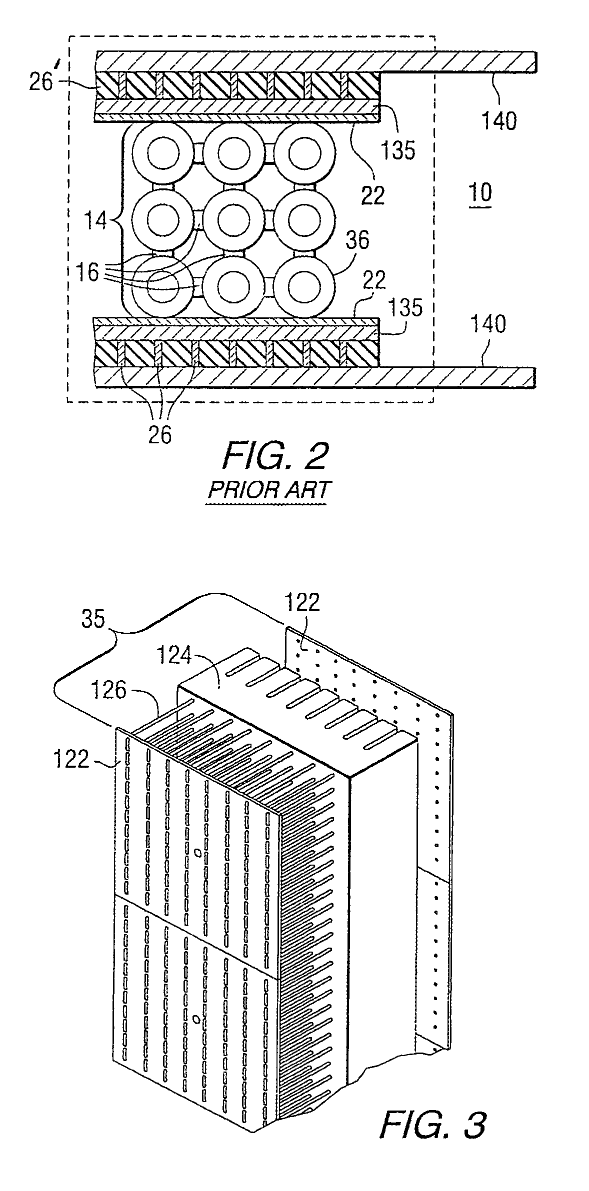
[0036] In order to better understand the preferred embodiments of this invention, it is advantageous to regress and discuss some similarities and dissimilarities vs. previous designs. Referring now to prior art FIG. 1, a side section of a solid oxide fuel cell generator 10 is shown. It contains a plurality of fuel cell stacks of fuel cells 36. Each fuel cell, in this embodiment, is in hollow, axially elongated form, preferably tubular as shown, having an open top end 37 and, as shown in this embodiment, a closed bottom end 38. Use of dual open ended fuel cells is also an option. The fuel cells contain interior self supporting air electrodes, usually of a nickel zirconia cermet, with solid electrolyte, usually comprising yttria stabilized zirconia, there between, as is well known in the art. The fuel cells operate on a feed oxidant 50, usually pre-heated air, and reformed fuel 12, usually internally or externally reformed to provide H2+CO anode gas, shown at the bottom of FIG. 1. The...


PUM


Abstract

A solid oxide fuel cell generator (10) is made which contains a plurality of bundles (14) of solid oxide fuel cells (36), the fuel cells, capable of generating electrical current, a bus bar unit (128) in adjacent contact with the plurality of fuel cell bundles at the sides of the generator, where the bus bar unit (128) can pass electrical current from the adjacent fuel cell bundles, the bus bar unit (128) containing inner flat plate / screen sections (130) near the fuel cell bundles, outer solid nickel bar (134) and with wide, solid, flexible, corrugated nickel strap electric current take-off connections (136) between the screens and bar; a power lead (140) electrically connected to the outer solid nickel bar, and also electrically through the bus bar unit to the fuel cell bundles through the take-off connections and inner screen sections; where the inner screen sections (130) and take-off connections (136) pass electrical current generated in the fuel cell bundles through the bus bar units (128) to an electricity receiving source.

Description

FIELD OF THE INVENTION [0001] The invention relates to improved electrical bus connection structures for bringing electrical power out of exterior fuel cell bundles of a high temperature fuel cell generator. The invention is more particularly directed passing electricity generated by high temperature solid electrolyte fuel cells which utilize an electrochemical combustion reaction between an oxidant and a fuel gas, which are combined at the fuel electrode to directly convert chemical energy of the fuel into direct current electrical energy. A typical such fuel cell reacts hydrogen and or carbon monoxide with the oxygen in air to produce electrical energy, water vapor and heat. BACKGROUND OF THE INVENTION [0002] Solid oxide electrolyte fuel cells operate at elevated temperatures of from about 700° C. to about 1100° C. in order to render the solid oxide electrolyte sufficiently conductive of negative oxygen ions to achieve high conversion efficiency, as taught, for example, in U.S. Pa...

Claims


Application Information

Patent Timeline
IPC IPC(8): H01M8/12H01M8/24
CPCH01M8/02H01M8/0202Y02E60/50H01M8/2465H01M8/243H01M8/2428
Inventor DRAPER, ROBERTJASZCAR, MICHAEL P.IYENGAR, ARUNDESAI, NIRANJANOSBORNE, CHARLES R.
Owner SIEMENS AG
Why Eureka
Try Eureka