Electric cable splicing system

a technology of electric cables and splicing devices, which is applied in the direction of workpiece holders, manufacturing tools, hoisting equipment, etc., can solve the problems of weak hands, no known device that can be used in splicing together, and inability to achieve strong hands

Inactive Publication Date: 2006-02-02
ZETTLE ELMER EDWARD
View PDF6 Cites 3 Cited by
  • Summary
  • Abstract
  • Description
  • Claims
  • Application Information

AI Technical Summary

Problems solved by technology

There is no known device that can be used in splicing together the above noted cables, other than hand tools, because they are large in diameter and the outer layer is made of a plastic or rubber material that must be and remain water resistant for obvious reasons.
The only way to slide the connection sleeve or housing over the splice is by hand because any tools used can damage the outer circumference which is highly undesirable and may distort the cable or the housing out of round whereby the integrity of the water tight fit is violated.
It takes extreme strong hands to accomplish the task of connection and it is very time consuming and labor intensive.

Method used


Image

  • Electric cable splicing system
  • Electric cable splicing system
  • Electric cable splicing system

Examples


Embodiment Construction

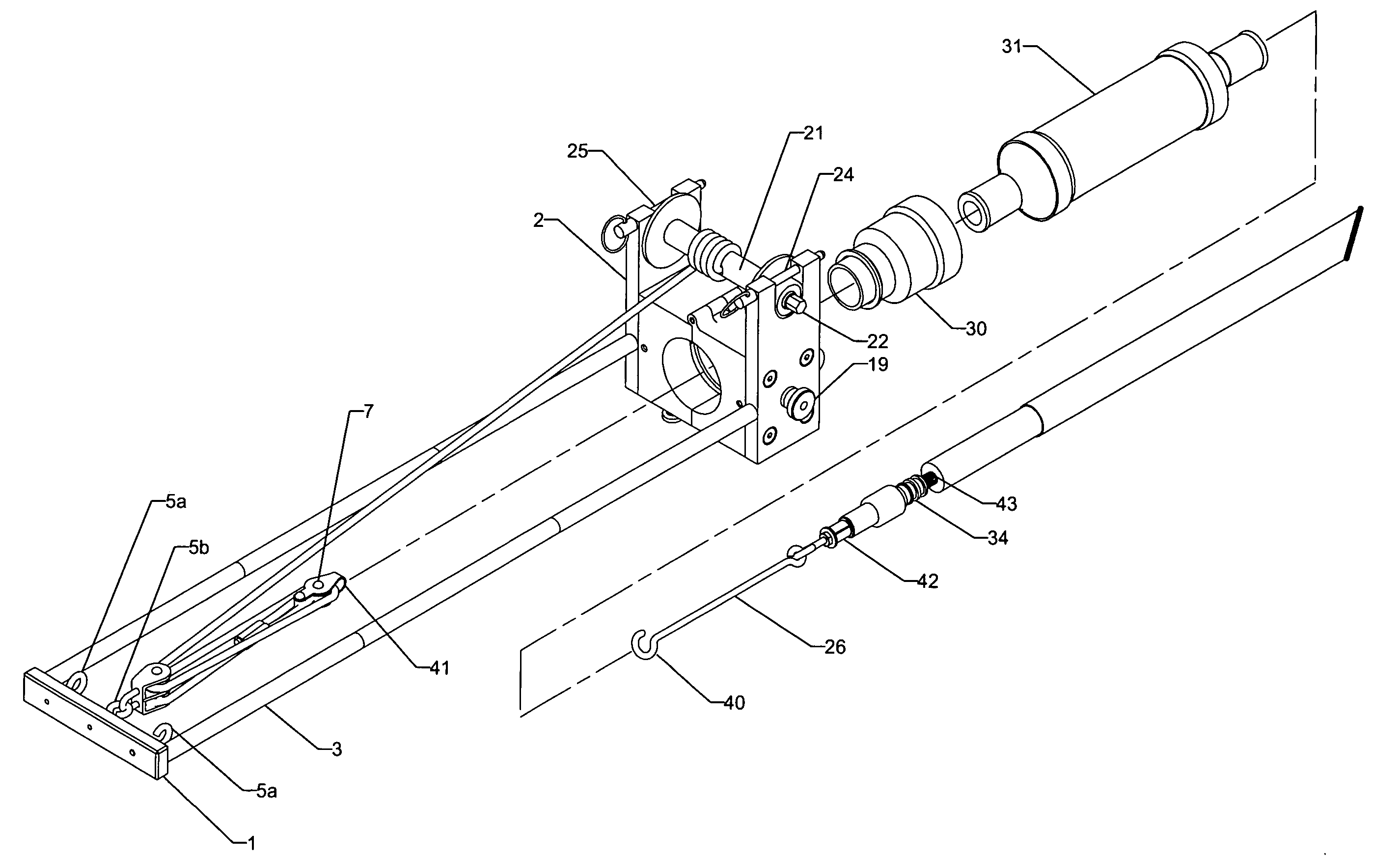
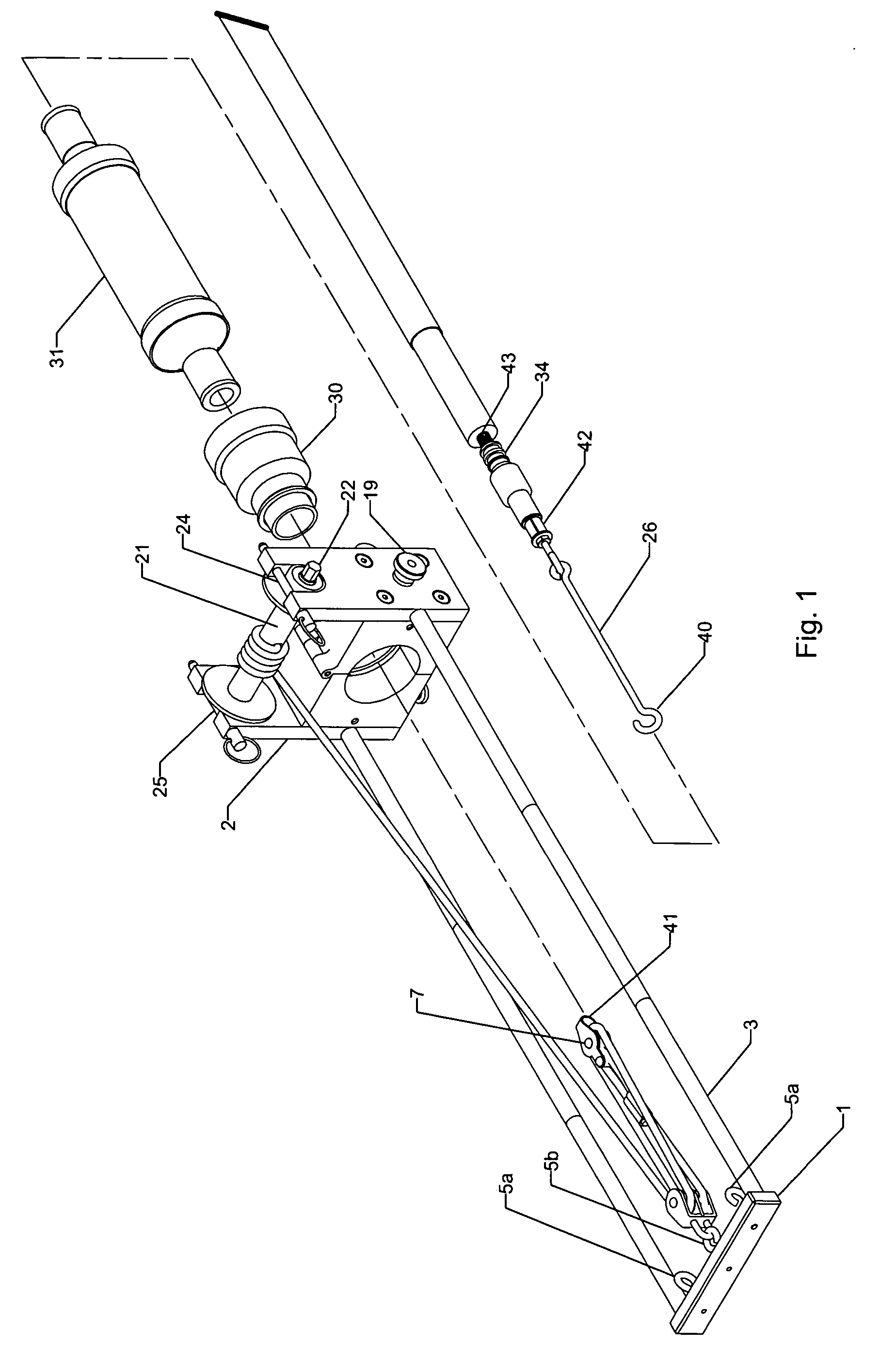
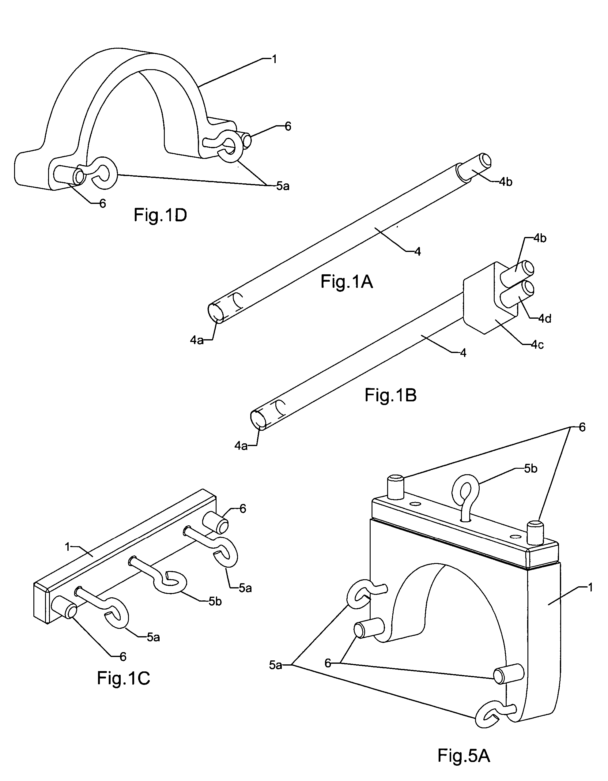
[0032]FIG. 1 illustrates a first stage of the process when splicing an electrical underground cable. The reason there are several stages is the fact that various pulling forces on the elements of the splice occur in different or opposite directions. In this first stage there is a stationary block 1 and there is a stationary clamping block 2. The reason why these blocks are stationary is that various elements that make up the splice have to move independently of the cable that is clamped or will be by the clamping block 2. Both the clamping block and the stationary block are held in their position by the static rods 3. The static block 1 is shown in more detail below in FIG. 1C. The static rods 3 are shown in more detail in FIGS. 1A and 1B below. The static block 1 consists of pegs 6 which can and will receive at least one end of the static bar 3 in FIG. 1. The pegs 6 can be threaded or be smooth depending of n the manufacturer. The clamping block 2 is made up of two halves 10 and 11...


PUM

PropertyMeasurementUnit
forceaaaaaaaaaa
frictionaaaaaaaaaa
flexibleaaaaaaaaaa

Abstract

A system for splicing together heavy duty electric cables, especially underground cables, consisting of a static friction block and a clamping friction block located on ends of cables to be spliced. A block and tackle mechanism is interposed between the friction block and the clamping block to provide a force to move various elements on the cables to various and final predetermined locations to make up the splice. The block and tackle mechanism has a wind-up spool thereon to wind-up ends of cords of the block and tackle mechanism. The wind-up spool provides the necessary force to accomplish the move of the various elements.

Description

BACKGROUND OF THE INVENTION [0001] This invention involves the splicing together of high power electrical wires or cables, especially underground cables. There is no known device that can be used in splicing together the above noted cables, other than hand tools, because they are large in diameter and the outer layer is made of a plastic or rubber material that must be and remain water resistant for obvious reasons. Most all of the connections made are made by hand, especially when applying a connection sleeve over the wire splice once they have been made. The connection sleeve or housing has to have an extreme tight fit to be water proof. The only way to slide the connection sleeve or housing over the splice is by hand because any tools used can damage the outer circumference which is highly undesirable and may distort the cable or the housing out of round whereby the integrity of the water tight fit is violated. It takes extreme strong hands to accomplish the task of connection an...

Claims


Application Information

Patent Timeline
Patent Type & Authority Applications(United States)
IPC IPC(8): B66D3/04
CPCH02G1/14Y10S269/903Y10T29/53243Y10T29/53265Y10T29/532Y10T29/53257Y10T29/53796
Inventor ZETTLE, ELMER EDWARD
Owner ZETTLE ELMER EDWARD
Why Eureka
Try Eureka